
Four isolated recognition checks
A identifies 36725. B separates the rear depth screw from the front bevel knob, with a ¼-inch projection ceiling. C identifies the single notch right-edge zero reference. D connects native adapter to an extractor and depicts disconnected supply.
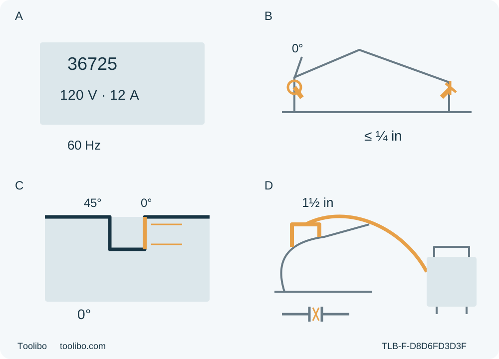
A · Establish original applicability
Physical 36725, supplied instructions and original assembly must match. The current 2.5 mm replacement card does not resolve the manual’s 2–2.1 mm teeth specification.
B · Lock two separate settings
Unplugged, use the rear depth screw and front bevel knob separately. Confirm actual breakthrough within the ¼-inch ceiling and lock zero for a supported scrap trial.
C · Qualify the right-edge reference
The single front notch uses its right edge for 0°. A real scrap-line test establishes alignment; no factory offset or finish guarantee is assumed.
D · Require active native capture
Existing complete native adapter/hose/extractor system must be qualified. Isolate for connection checks, then operate the extractor under its instructions before cutting.
Original conceptual recognition, not to scale and not a live cut or installation procedure. B requires actual through-cut clearance no greater than ¼ inch below the stock, not a fixed target or an imported full-tooth rule. C shows reference edges, not a measured kerf; the actual scrap trial establishes line alignment. D means an already qualified native 1½-inch outer-diameter adapter system with suitable active extraction, not arbitrary hose compatibility. Every adjustment/connection check is OFF, fully stopped and unplugged, with extractor isolated.
A useful first result with a matched WEN 36725 is a modest, supported square crosscut whose line, angle and separated pieces can be inspected—not a demonstration of maximum depth. This workflow starts with an existing, correctly assembled owner system. It does not teach blade installation, a dust-port retrofit or electrical work.
1. Establish which 36725 system you actually own
Match the physical model, controls, nameplate and complete supplied instructions to the 20-page 36725 manual linked from the US product page. Its filename contains 20180830; that alone does not establish a printed revision date or applicability to every later unit. The documented supply is AC 120 V, 60 Hz, 12 A and the motor’s no-load speed is 4500 RPM. An unmatched machine or document is a reason to stop, not to borrow a similar saw’s procedure.
The retained original wood assembly must already be positively identified and correctly fitted: the manual lists a 24-tooth TCT blade, 7¼ inches (printed 185 mm), with a 5⁄8-inch (15.875 mm) bore, a 1.3–1.4 mm body and 2–2.1 mm teeth. Its parts list names 36725B. The current related replacement card instead describes a 2.5 mm thickness. The repeated part number does not resolve that discrepancy. This article does not approve buying or fitting that replacement, changing washers or adapting the bore. Nor does a current replacement card’s speed marking establish the rating of an older installed blade. If the actual original blade, its approval, condition or mounting cannot be established, obtain qualified correction before using the saw.
Use only known, clean, dry, uncoated loose wood for this sample, with the actual original blade approved for it. Inspect the entire proposed route and remaining stock for nails, screws and other foreign material. Reject unknown coatings, contamination or concealed objects. Interior plunge cuts, bevel cuts, installed structures and nonwood materials are outside this workflow.
2. Qualify supply, personal protection and dust control
The actual nameplate supply, sound cord and polarized plug, GFCI protection and the complete manual’s branch-circuit requirements must already be satisfied. Have an appropriately qualified person resolve any uncertainty. Do not modify a plug, select a fuse by guesswork or treat double insulation as permission to use the tool in damp conditions. If an extension is necessary, its complete length, rating, condition and wiring must meet the manual’s electrical requirements; this is not a wiring or extension-selection tutorial. Keep the tool, workplace and hands dry and away from rain, wet areas and flammable gases, liquids or combustible dust atmospheres.
Wear ANSI Z87.1 eye protection, appropriate hearing protection and the dust mask required by the manual. Arrange ventilation and material-appropriate dust control, not merely an open door. Keep bystanders, children and pets outside the work area. Secure hair and remove loose clothing and jewelry; maintain stable, nonslip footing. The manual’s general glove statements are inconsistent across phases. Do not bring gloves or other entanglement hazards into powered operation. Its sharp-blade handling glove instruction belongs to isolated, cooled maintenance handling, not to holding a running saw or clearing chips.
Wood dust collection is a prerequisite here. The complete native dust-port arrangement, including the existing 36725-028 adapter, must already be correctly established under the actual tool and extractor instructions. The manual gives the adapter’s outer diameter as 1½ inches. That is not proof that an arbitrary hose fits, and no airflow or filtration certification is inferred from the number. Require a suitable extractor and secure hose connection for the actual wood and dust. Missing hardware, uncertain compatibility or unavailable suitable extraction means HOLD before cutting, not a mask-only substitute.
Make and check hose connections only with the saw OFF, fully stopped and unplugged, and with the extractor isolated under its own instructions. Route hose and cord away from the blade, guard, cut and walking path. They must remain free through the complete feed and exit. Activate and check the qualified extractor under its instructions before the cut; a connected but inactive hose is not dust control.
3. Inspect the isolated saw and the complete support route
With the switch OFF, blade completely stopped and plug disconnected, inspect the accessible tool, cord, controls and original mounting condition. The switch must work correctly and return to OFF; remove setup tools before reconnection. Do not proceed with loose or uncertain hardware, a dull, rusty, chipped or damaged blade, a bent base, abnormal binding or unexplained vibration. A known fault requires qualified assessment, not a powered attempt to reproduce it. Smoke, sparks or unusual odor are not accepted as a normal break-in exercise in this workflow.
Use the lower-guard lever only for the prescribed isolated guard check. Confirm free movement, immediate closure and clearance from the blade and other parts through all documented angles and depths. After a drop, additionally check for damage and the same unrestricted movement. A sticky, damaged or uncertain guard means no use until corrected. Never tie it open. For the ordinary edge-entry cuts below, the lower guard must operate automatically; do not hold it open by hand.
Choose a manageable scrap with enough retained area for the base and both grips to remain controlled throughout the cut. Place its good/appearance face down, as the manual requires; this does not guarantee an undamaged finish on either face. Secure the retained stock with clamps on stable supports. Independently support the portion that will separate, with supports close enough to prevent sagging or kerf closure but outside the entire blade path. Waste must separate freely without pulling the saw, dropping unpredictably or being clamped across a closing kerf. No hand, knee or helper substitutes for support, and nobody reaches beneath the work.
The manual places the operator to the left of the saw, with the cut on the operator’s right and the motor over the larger retained portion. Qualify that actual arrangement, not a mirrored sketch from another saw. Check the entry, middle and exit for full shoe support, clamp clearance, both-handle reach, stable footing and free cord/hose travel. Conduct any isolated reach assessment beside or safely above the intended route with the blade guarded and no tooth contact; do not push an unplugged blade into stock or force its guard open. If the complete supported route cannot be established, use a different qualified setup or postpone the cut.
4. Set the rear screw and front knob separately
Keep the plug disconnected. The rear depth locking screw belongs to the depth bracket; it is not a quick-release lever. Loosen it, move the base to the needed depth using the bracket and the ridge on the inner upper guard as the documented reference, then tighten the screw securely. Check the actual relationship to the stock and support clearance rather than trusting the scale alone.
The WEN instruction is a through-cut with the blade extending no more than ¼ inch below the stock. Choose only the clearance needed for the actual cut within that ceiling. The manual’s example for 2-inch stock is around 2⅛ inches of depth, never deeper than 2¼ inches. This is an example, not a universal ⅛-inch setting. This particular source does not state the less-than-full-tooth rule used by some other saws; do not misattribute it to WEN or substitute another model’s scale. Excessive projection increases kickback risk, while insufficient depth leaves the pieces joined.
At the front, loosen the separate bevel adjustment knob, set the top edge of the indicator bar to zero and securely tighten the knob. This guide uses only a square cut. Confirm the setting with the supported scrap cut and measure the resulting angle before cutting the intended piece; it is not a calibration or high-angle tutorial.
The front line-of-cut notch uses its right edge for 0° and left edge for 45°. Only the right-edge reference is used here. The manual requires a scrap-line trial because the real blade and kerf affect the relationship between the mark and the cut. Mark the retained side and waste clearly. Establish that relationship on the actual supported sample rather than assuming a factory offset or guaranteed line accuracy. The included rip guide’s installation is not part of this crosscut workflow.
5. Make one controlled edge-entry sample
Before connecting power, verify OFF, a fully closed guard, secure depth and bevel settings, removed setup tools, sound original assembly, the clear cut path and active qualified dust control. Take the front and rear handles, using their insulated grip surfaces; keep both hands out of the cutting area, away from the blade and out from under the work. Neither hand may obstruct guard movement. Stand on the left as specified, without leaning into the blade line.
Rest the front of the base securely on the supported retained stock with the blade clear of the edge. Press and hold the safety lock button, then squeeze and hold the power switch. Allow full speed before blade contact. Advance gently along the qualified line, keeping the base flat and both grips secure. Let the saw cut without forcing it or twisting it sideways to chase a drifting line. Continue only while the retained base support, independently supported waste, guard, cord and hose remain controlled through full separation.
For normal completion, release the switch and wait for the blade to stop completely before withdrawing or lifting the saw. Confirm the lower guard covers the blade before setting the saw down securely, then unplug it before inspection. Do not judge readiness by sound alone or assume an electric-brake time not established by this manual.
For binding, interrupted feed, lost support, a badly drifting line or any other abnormal condition, release the switch immediately and hold the saw motionless until complete standstill. Do not lift or pull a moving blade out of the kerf. Disconnect power before assessing the cause. An unclear release, damaged assembly or unsafe remaining setup goes to qualified assistance; this article does not teach trapped-tool extraction or restarting in an old kerf.
6. Accept the result, or keep the system out of use
With the saw unplugged and the blade cooled, inspect both pieces without touching sharp edges. Check complete separation, the line and actual dimensions, squareness through the thickness, and both faces for tearing, burning or damage. Confirm that neither portion sagged into the kerf and that the depth screw, bevel knob, guard and dust connection remained sound. A visually straight edge alone does not establish a satisfactory process.
Accept the sample only if the intended geometry and surface condition are suitable and every support/control condition remained qualified. If the line relation or angle is wrong but the tool is otherwise sound, make only the documented isolated setting correction and use a fresh, properly supported sample. Do not salvage a small loose offcut by holding it for a recut. Any unexplained vibration, overheating, binding, persistent burn or movement of settings requires a hold and appropriate investigation rather than more force or repeated trials.
After use, keep the saw unplugged, clean exterior surfaces with a soft cloth and keep accessible ventilation openings clear without reaching into moving-part areas. Do not introduce solvent, water, internal compressed-air cleaning or a brush-replacement exercise. Store the cooled tool dry and inaccessible to children. Blade replacement, spindle locking, torque, electrical repair and internal maintenance remain outside this owner workflow. Record the actual document, retained blade qualification, dust system and sample result so that a later component change triggers a fresh applicability check instead of automatic reuse of today’s acceptance.
Models referenced