
Two forward passes with an isolated transition
A shallow 2–3 mm groove, a disconnected transition, a full-depth forward cut and inspection of the retained edge.
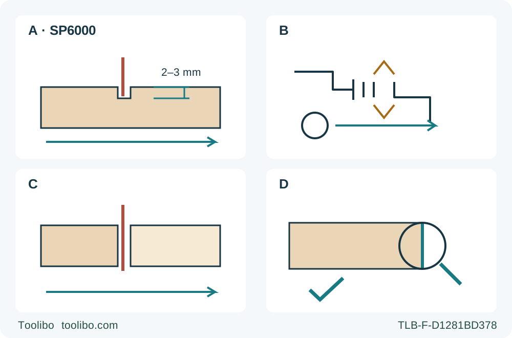
A · Make the documented shallow pass
With the original system and commissioned rail qualified, select the quick stop while unplugged; start clear at the edge and advance forward for the 2–3 mm first pass.
B · Isolate before the transition
Release the trigger, wait for standstill and enclosure, unplug and inspect. Pull the quick-stop button back only while isolated; recheck normal depth and unchanged support/rail.
C · Complete the normal forward pass
Return the guarded isolated saw to the supported start, then use the ordinary start sequence and verified through depth along the same rail; never reverse-feed.
D · Inspect the whole result
After standstill, enclosure and unplugging, check both faces, retained dimensions and correspondence of shallow and full-depth paths. Reject drift or unsafe behaviour.
The sections are conceptual depth and sequence diagrams, not a physical blade-side plan or support layout. A is the documented 2–3 mm limit only with the guide rail. B requires complete standstill, blade enclosure and unplugging before the button change and return to the start. C remains forward with the same fixed rail and verified normal depth. The D check is project acceptance, not a manufacturer finish guarantee.
The SP6000’s shallow first pass is a specific documented function, not permission to pull a running saw backward or guess a scoring depth on another tool. Makita describes a quick-stop button that limits the cut to 2–3 mm when the saw is used with its guide rail, followed by another pass at normal cutting depth. The two passes must share a stable reference if they are to produce a useful finished edge.
This workflow uses an existing US SP6000 under manual 884683E949, with its correctly fitted original wood blade, one already commissioned genuine rail and the correct clamps and complete accessory instructions. The output is a fully separated square-cut sample with an inspected scored edge and retained dimensions. It excludes internal plunge starts, reverse scoring, rail joining, bevel cuts and blade replacement. A rail whose splinterguard has not yet been correctly commissioned needs that separate task first.
Decide whether this sample can support two passes
Choose known clean wood or a wood panel suitable for the installed blade, with a sound surface and enough area to support the rail, saw and clamps. The material must be thick enough that the documented shallow pass does not become an unintended through cut. Establish that from the actual material and cutting arrangement, not from a nominal label. Unknown coatings, fasteners, damaged layers or uncertain blade suitability stop this workflow.
Mark the retained side, waste and required final line. The purpose is to compare the finished edge with the project’s actual requirements, not to manufacture a universal “splinter-free” claim. Decide which face and corners matter before cutting, and record any pre-existing damage. A clean top edge with an unacceptable opposite face or wrong retained width is not a successful result.
Plan both stages before connecting power. The first pass leaves the work largely connected; the second separates it. Both portions still need appropriate support through that final separation, outside the blade path, with the retained portion carrying the rail and base. Clamp the retained work securely and let the waste separate without closing the kerf. Do not rely on the thin uncut section after scoring as a substitute for support.
Reconfirm the commissioned rail and isolated controls
Switch off and unplug for every inspection or adjustment. Match the actual nameplate supply and inspect the cord. Keep the original 165 mm/20 mm US assembly qualified, with a blade rated at least 5200 rpm even if a lower speed setting is used. Do not infer fitting approval from those two dimensions alone. A damaged blade, uncertain flanges or an unexplained change in the splinterguard reference requires proper resolution before either pass.
Use the actual documented genuine rail and clamps, not a look-alike track. The current US product lists rails 194368-5 and 194367-7 and clamp set 194385-5; these establish listed compatibility, not what any carton contains. The complete accessory instructions and previously accepted full-length splinterguard edge remain prerequisites. This task does not teach their initial assembly or repair.
Check the two rail-fit screws for smooth sliding without clatter, rather than tightening them until movement becomes stiff. Keep the rail seated and clamped at the intended line for both passes. Clamp bodies, cord and the qualified connected extraction hose must clear the whole travel and must not tug the saw or move the rail. Assess the route while unplugged with the head returned and blade enclosed; do not push exposed teeth into stock for rehearsal.
Check trigger return, free head movement, guard closure and the return spring. With the saw isolated, also verify that the guard clears the blade and other parts at all angles and depths of cut. The saw must enclose the blade normally; the blade-change locking arrangement is not used to hold the head down for cutting. A sticking return or guard is a stop condition. Set zero bevel and securely lock both front and rear clamping screws. Do not use the bevel anti-tip lever as a substitute for proper rail fit and clamping.
Establish the normal depth, then the shallow limit
The normal-depth control is the clamping screw and blade lower-limit stopper. With power disconnected, establish the through-cut depth for the actual work and rail, secure the screw and verify actual projection. The manual calls the scale a rough guide. Do not add an assumed rail thickness to a remembered setting. Use less than a full tooth below the wood, satisfying the stricter safety wording as well as the setup section’s no-more-than-one-tooth condition.
Keep fingers out of the tooth path during the isolated check and return the head to its guarded position afterward. If you cannot verify the depth safely with the complete instructions, hold the sample. The blade must not reach supports, clamps, the bench or floor during the eventual through pass.
For the first pass, push the quick-stop button toward the saw blade while unplugged. Under the stated rail condition, this selects the documented 2–3 mm shallow cut. It is not the main depth stopper, an emergency stop or the blade-change lock. This article does not substitute a product page’s approximate inch wording for the manual’s range, and it does not transfer the range to operation without the rail.
Retain a speed already established as appropriate for the actual wood and approved blade under their instructions. The dial runs from 1 to 6; the manual does not prescribe one universal wood setting. Do not force it beyond its limits or use a lower dial setting to justify a lower-rated blade. Keep eye, hearing and appropriate respiratory protection, ventilation and qualified extraction in place throughout both passes.
Make the first pass forward from the edge
Start at the supported rail entry with the blade clear of the material. Hold the front grip and rear handle, keep your body to either side of the blade line and do not place a hand beneath the base or on the work. Connect power only after all setup checks are complete. Operate the lock-off and trigger, wait for full speed, then lower the head slowly to the selected shallow stop and advance forward smoothly along the rail.
Keep the base flat and the rail fixed. Do not twist the saw to chase a mark or force it through resistance. The shallow pass is still a powered saw cut, not a harmless pencil line. Never pull the running saw backward to score against its ordinary feed direction.
At the normal end, release the trigger and maintain control until complete standstill and blade enclosure before moving or setting down the saw. Unplug before inspecting the shallow groove or changing the quick-stop button. If binding, rail movement or another abnormality interrupted the pass, release the trigger and hold the saw motionless until stopped; do not withdraw a rotating blade. That event ends this two-pass plan until its cause is resolved under the full instructions. No interrupted-kerf restart is taught here.
Inspect the first pass and change modes while isolated
Confirm that the first pass produced the expected shallow continuous groove and did not separate the work unexpectedly. Look for rail movement, a wandering groove, damaged surface or anything indicating that the actual setup differs from the qualified one. Do not proceed merely because the first line is visible. An incorrect first pass cannot be made acceptable by forcing the through pass to follow it.
Keep the work and rail clamped in the same accepted position. With the saw unplugged and its blade enclosed, pull the quick-stop button back to release the shallow restriction. Reconfirm the previously established normal-depth stopper, both bevel locks, rail fit, support and the full-depth clearance. Changing the button is not permission to change the rail position or assume the depth lock stayed secure.
Return the isolated, guarded saw to the supported starting position without dragging exposed teeth through the groove. Recheck the cord and hose route. The second pass begins as another ordinary edge-start cut with the blade clear, not as an internal plunge into the shallow groove.
Complete the through pass and accept the result
Using the same controlled starting sequence, wait for full speed, lower to the verified normal depth and advance forward along the unchanged rail. Support must remain effective as the offcut separates. Do not reach for the waste or move a clamp while the blade is running. After normal completion, release the trigger, wait for full standstill and blade enclosure, set down safely and unplug before handling the result.
Inspect the retained edge along its full length, both faces and the entry and exit corners. Check the intended width, straightness and square cut through the thickness. A visible mismatch between the shallow and full-depth paths, loose veneer, excessive damage or a shifted dimension means the sample has not passed. This guide sets no manufacturer tolerance or guaranteed finish grade.
Record the actual saw, original blade, rail, panel, speed, normal-depth verification, quick-stop use and observations after each pass. A successful result supports using this same established two-pass method for the documented task; it does not qualify another blade, rail or material automatically. If the result is unacceptable, keep the tool isolated while separating setup, material and tool-condition questions. Do not add reverse feed, extra depth or an improvised third pass as an unverified remedy. The complete outcome is a correctly separated and accepted sample—or a clear hold before valuable work is attempted.
Models referenced