
Four checks before trusting a rail edge
A shows an isolated SP6000; B identifies both rail-fit screws; C shows the full strip length as a reference to establish; D checks the completed edge and a second sample.
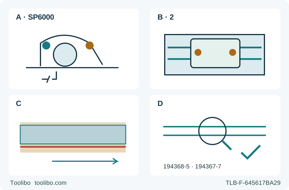
A · Isolate and qualify
Switch off and unplug. Retain the correct original assembly and verify free return, complete guarding, trigger return and both zero-bevel clamps.
B · Adjust the paired fit
Set both base adjusting screws so the actual rail permits smooth travel without clatter. Rehearse the full path while isolated; do not create drag.
C · Establish the full reference
With actual rail-inclusive depth verified and less than a full tooth below wood, trim the splinterguard in one supported forward pass along the full rail length.
D · Verify before production
After standstill and unplugging, inspect the strip and rail seating. Align a second sample to the trimmed edge and accept only stable, dimensionally consistent square results.
These are conceptual checks, not a running-cut plan or a blade-fitting tutorial. A means switched off and physically unplugged. B requires smooth travel without clatter, not maximum screw tension. C represents the full-length splinterguard trim with support and clamping established in the body; the arrow denotes reference length, not a blade-side layout. D means inspect after standstill and unplugging, then verify a separate supported sample. The rail numbers identify listed genuine accessories, not a carton promise.
A new splinterguard edge is not automatically a trustworthy cutting reference. On the US Makita SP6000, the saw must first slide correctly on its actual rail, the depth must be established with that rail in place, and the strip must be trimmed under controlled support. A second sample then shows whether the resulting edge can locate a real cut. This workflow ends with that documented acceptance, not merely with a motor that runs.
It applies to an existing SP6000 matching instruction manual 884683E949, the tool listed in the US SP6000J configuration. Keep its correctly installed original wood blade and mounting assembly. Use one genuine listed rail, with its correct clamps and complete accessory instructions already available. This is a square, edge-start wood task; it does not teach rail joining, internal plunge cuts, bevel cutting, replacement blades or a two-pass scoring technique.
Qualify the actual saw, rail and electrical supply
The US product identifies a 165 mm blade and 20 mm arbor. The manual requires a blade rated for at least 5200 rpm even when a lower dial setting will be used. A slower selected speed does not authorize a lower-rated blade. If the installed blade, flanges, fastening, rotation or suitability for the intended wood is uncertain, stop and resolve the complete assembly against the supplied instructions. Do not infer a replacement procedure from a diameter alone.
The current US product lists genuine rails 194368-5 and 194367-7 and clamp set 194385-5. These are compatibility evidence, not a promise that any particular carton contains them. Identify the actual rail and clamps. Reject bent or damaged running surfaces, loose or damaged splinterguard material and unexplained accessory modifications. Have the correct complete rail and clamp instructions; this article does not supply missing connector, clamp-fitting or rail-repair directions. Do not substitute an unverified other-brand rail because it looks similar.
Match the actual nameplate voltage and frequency to the supply. The US listing’s 12 A rating is not a universal regional voltage statement. Inspect the cord and plug and use a suitable extension arrangement under the manual, if one is needed. Keep the work dry. Switch off and physically unplug before inspecting, adjusting or checking the saw. A released trigger and its lock-off button are not electrical isolation.
Check return, guarding and the controls before rail work
With power disconnected, verify that the trigger moves freely and returns to OFF when released. Check the guard and return spring as the manual requires: movement must be free, closure immediate and complete, and the blade must not contact the guard or another part at all angles and depths of cut. Never tie or clamp the guard open. A slow return, sticking plunge movement or damaged spring is a stop condition, not something to overcome with more force.
Retain the ordinary operating configuration. The blade-change locking arrangement is not a device for holding the head down during normal cutting. This guide does not use it to expose or replace the blade. Confirm that the head can return normally and enclose the blade when released. Keep hands away from the teeth during all checks.
Set zero bevel with both the front and rear clamping screws secured. Do not tighten only the visible front screw and assume the rear follows it. The positive stops, additional 48-degree lever and negative-angle shifting levers belong to other settings; they do not establish this square setup. If zero cannot be held reliably, obtain proper correction rather than adjusting factory calibration screws as part of commissioning.
Make the support plan before adjusting the fit
Use clean, known wood large enough to support the rail and saw throughout the planned pass. Choose a manageable sample rather than a finished panel whose value encourages rushing. Inspect for fasteners, foreign objects and hazardous finishes. Mark the retained side and waste side and establish where the cut will finish. The rail needs a stable seat; rocking stock cannot be corrected by clamping the rail harder.
Support the work so neither side sags into the kerf and the retained piece continues carrying the rail and saw base as separation finishes. Keep every support and clamp clear of the blade’s full path below the stock. The offcut must not be trapped or forced against the blade. Do not hold the work by hand or across a leg. This guide assigns no support load rating and does not assume an arbitrary foam sheet is suitable underlay.
Secure the work and the rail using the actual approved clamping arrangement. Confirm that clamp bodies and handles cannot collide with the base, motor housing or planned hose route. Allow enough rail and stable support for the saw’s start and exit positions; do not invent a universal overhang distance. If the supplied accessory instructions and actual geometry cannot establish those positions, choose a suitable sample arrangement before powering the tool.
Adjust both rail-fit screws without creating drag
With the saw unplugged and the blade enclosed, place the tool at the rear end of the guide rail as shown in the manual. Adjust the two screws on the base so the saw slides smoothly without clatter. This is a paired fit check: removing play at one end while leaving the other loose does not establish the whole base. Conversely, tightening until travel becomes stiff is not greater accuracy.
Slide through the intended travel while isolated, checking for binding, rocking and changing resistance. Recheck clamp clearance and support during this rehearsal. Route the cord and connected extractor hose so neither can pull the saw sideways, catch a rail end or enter the cutting path. The hose must actually fit the dust port; conflicting marketing dimensions are not a reason to force an adapter. Keep extraction operating for the sample, with appropriate eye, hearing and respiratory protection and ventilation.
The rail’s anti-tip slide lever is described for engaging the undercut groove during bevel cutting. It does not replace the fit screws or clamps. This zero-degree task does not borrow a bevel procedure or treat that lever as a universal safety lock.
Establish actual depth with the rail in the stack
The depth adjustment uses a clamping screw and blade lower-limit stopper. With power disconnected, loosen the screw, position the stopper, then secure the screw. The manual explicitly calls its scale a rough guide and requires actual blade projection to be measured for accuracy. Account for the actual rail between base and work rather than adding an assumed rail thickness to a remembered setting.
Use the stricter safety condition: less than a full blade tooth should project below the wood. The setup section also says no more than one tooth; the less-than-full-tooth condition satisfies both. Arrange the isolated check without fingers in the tooth path and return the head to its guarded position afterward. Recheck the locked setting before the powered pass.
Recognize the quick-stop button but do not confuse it with the main depth stopper. Pushing it toward the blade restricts a first pass to 2–3 mm when using the guide rail; pulling it back releases that restriction for normal depth. This commissioning workflow uses the correctly preset normal-depth configuration, not a guessed scoring setting. It does not turn the product overview’s approximate inch wording into an exact conversion or teach a reverse scoring pass.
Select speed for the actual wood and approved blade under their instructions. The dial runs from 1 to 6, corresponding to 2000 through 5200 rpm; do not force it beyond its stops. The manual does not give a single universal wood setting. Soft start and constant-speed control do not compensate for an unsuitable blade, excessive feed or a loose rail.
Trim the splinterguard in one controlled forward pass
The manual’s rail commissioning instruction is to trim the splinterguard along the full rail length in one stroke, after the sliding fit is established. Prepare the supported sample and clear travel accordingly. The untrimmed edge is not yet a final dimensional reference; do not place valuable work by assuming it already represents the kerf.
At the supported edge-start position, with the blade clear of the wood, hold the front grip and rear handle. Operate the lock-off and trigger and wait for full speed. Lower the head slowly to the preset depth, then advance forward smoothly, keeping the base flat and the rail seated. Use both hands on the provided grips; neither hand steadies the stock or reaches under the base. Maintain a straight path without twisting, forcing or trying to steer the saw back onto a line.
Plan to complete the full pass without losing support. At normal completion, release the trigger, maintain control and wait for complete standstill and blade enclosure before moving or setting down the saw. If binding, unexpected movement or an abnormal stop interrupts the cut, release the trigger and hold the tool motionless until the blade stops. Do not withdraw a rotating blade or restart merely because electrical overload protection operated. Unplug before inspecting and resolve the cause; an unresolved fault ends this session.
Verify the reference with a second sample
After standstill, unplug. Inspect the trimmed strip and rail seating along the whole length. A ragged, detached or inconsistently trimmed edge is not a reliable measuring aid. Check the fit screws remain correctly adjusted and that the rail did not shift. Record the actual rail, installed blade and zero-bevel configuration rather than declaring every compatible saw interchangeable with this edge.
For a separate sample, mark the intended retained edge accurately, position the now-trimmed splinterguard edge to that line, and repeat the support, clamp, clearance and isolated depth checks. On the base’s front sight, the manual uses A for straight cuts with the rail; do not confuse it with the separate A/B marks on the guard side. Those side marks describe blade extent only at maximum depth with the rail and specified blade diameters, not universal endpoints for this sample.
Make the ordinary forward sample under the same controlled conditions. After full stop and unplugging, measure the retained piece at more than one position and check its edge and squareness against the intended result. Acceptance requires stable rail fit, no movement or binding, an intact usable strip reference, consistent width and a square cut appropriate to the project. This is a practical acceptance check, not a manufacturer tolerance claim.
If it fails, keep power disconnected while separating causes: rail position, clamping, support, depth, fit, blade condition or a tool requiring qualified correction. Do not hide a shifted rail by changing marks until one piece happens to fit. Only a verified second sample makes the commissioned edge a useful reference for subsequent work in the same established configuration.
Models referenced