
Separate four kinds of evidence
A identifies the original 7-1/4 in blade, round 5/8 in arbor and minimum 5300 rpm rating; B distinguishes left 45-degree and right 90-degree notch edges from an illustrative laser line; C measures the actual sample; D separates a power lamp from disconnection and standstill.
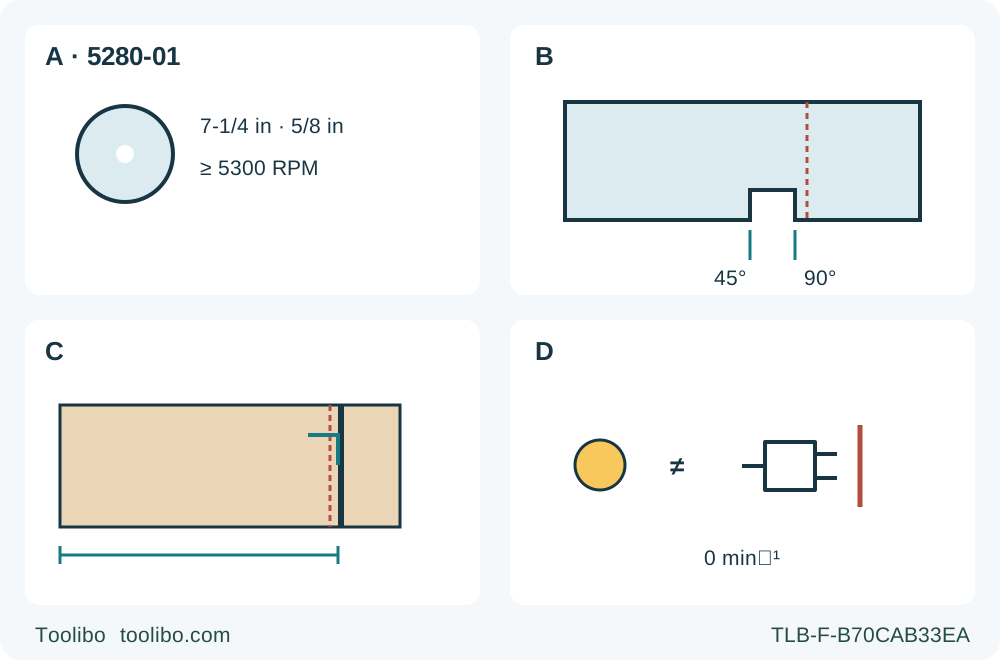
A · Qualify the original assembly
Keep the correct original 7-1/4 in, round 5/8 in wood assembly with a blade rated at least 5300 rpm. Uncertain clutch or fitting requires complete instructions or authorized correction.
B · Distinguish the references
At zero bevel the right notch edge is the approximate mechanical reference. The laser is factory set for the supplied blade; do not adjust it to force agreement with the notch.
C · Measure the actual sample
After complete stop and unplugging, compare the retained edge, width and square result with the intended mark. Repeat on another supported sample before important work.
D · Separate indication from isolation
The laser requires plugged-in power and its button; the power lamp only indicates supply. Complete mechanical setup unplugged and wait for standstill and guard closure before setting down.
A is an installed-assembly qualification, not a tightening recipe. B shows that the laser and notch may differ; the drawn spacing is illustrative, not a factory offset or adjustment target. The 45-degree label identifies the other notch edge but this task stays square. C is an unplugged, stopped sample measurement, not a running-cut plan or blade-side claim. D means neither an illuminated nor dark power indicator establishes safe isolation or complete blade stop.
The SKIL 5280-01 has three different things that can look like a cutting instruction: a projected laser line, the foot’s guide notch and the edge of the kerf left in wood. They are not interchangeable. The laser is factory set for the supplied blade, while the notch is an approximate mechanical reference. Only a supported sample shows where this actual, correctly assembled saw removes material.
This workflow takes an existing US 5280-01 matching the 03/22 manual from isolated inspection to a square wood sample and a recorded reference check. It retains the correctly installed original blade, washers and clutch setting. It does not teach blade replacement, clutch adjustment, laser calibration, internal plunge cuts or restarting an interrupted cut. The advertised 51-degree capacity is not an instruction to bypass a stop: the manual’s adjustment procedure describes up to 45 degrees. This task stays at zero bevel.
Establish the original assembly and supply
Check the actual model and nameplate before using a borrowed or previously owned saw. The specified blade is 7-1/4 in with a round 5/8 in arbor hole, and its speed rating must be at least 5300 rpm. These are simultaneous requirements, not alternatives. Keep the correct installed wood blade and original matched washers and bolt. A different arbor shape, improvised reducer, damaged washer or uncertain previous assembly is a reason to stop and obtain the complete correct instructions or authorized correction.
The Vari-Torque clutch operates through friction between the outer washer and blade. It is not an electronic kickback detector. Its effectiveness depends on correct assembly, and the manual warns that excessive tightening defeats it. Do not apply a generic maximum-tightness rule, try to induce slipping or tighten a slipping blade experimentally during this reference exercise. Unexpected slip or assembly uncertainty ends the sample plan until properly resolved. A clutch never makes unstable workholding acceptable.
Use the actual nameplate-approved AC supply and an undamaged matching plug and cord. This bounded setup assumes a suitably located direct supply, not an extension-cord sizing exercise. Do not extrapolate the blank entries in the manual’s extension table. Keep the work dry, and inspect cord routing before the tool is connected. Switch off and physically unplug for every setting change, inspection or accessory adjustment.
Check the guard and establish a square setup
With the plug removed, use the lower-guard lift lever to check free movement and immediate complete closure. The guard must clear the blade and other parts at all angles and depths of cut. A bent guard, slow spring return or packed debris requires correction before use. Never tie the guard open. During this ordinary edge-start cut it should operate automatically; manual retraction is not part of the workflow.
Check trigger return and the safety release without power. The release can be pressed with the thumb from either side before the trigger is pulled; releasing the trigger automatically re-engages the safety switch. That interlock helps prevent an unintended start, but does not disconnect the tool. A defective switch is not something to work around. If the tool fails to switch on or off correctly, disconnect it and have it repaired.
The front wing nut locks the bevel quadrant. Set zero and tighten it securely. The manual’s isolated square check uses maximum depth and a square between blade and the bottom plane of the foot. If performing that check, keep clear of the teeth and maintain unplugged status; afterward restore the actual cutting depth. A failed check is a stop condition here. The manual’s separate bend-tab correction is not included as a novice calibration recipe.
Set cutting depth with the lever between the handle and guard. While unplugged, hold the foot down and raise or lower the saw by its handle, then secure the lever and check the actual result. Use less than a full tooth below the workpiece. This follows the safety section’s stricter wording rather than copying the setup illustration’s full-tooth exposure. A lumber-size scale does not replace checking the thickness and projection on this piece.
Build a stable reference sample
Choose clean, known, uncoated wood or a wood panel suitable for the installed blade. Reject fasteners, unknown inclusions and hazardous finishes. Use a manageable sample with enough retained area to support the broad portion of the foot through the exit. Mark the required retained edge and the waste side, so that a line-width decision does not accidentally shorten the finished piece.
Support both sides appropriately near the cut and near panel edges, keeping supports outside the blade path. The manual shows broad faces of two-by-fours supporting the panel and resting on the bench, not narrow edges that make the arrangement unstable. Keep the blade clear of the bench and floor. The offcut must not sag into the kerf or be constrained against the blade. Secure the work with clamps; never hold it across a leg or use a free hand as a clamp.
For the supported rip-reference sample, use the manual’s straight 1 in (25 mm) lumber board guide against the right side of the foot, secured with clamps. Do not assume a track adapter or optional rip fence is already included. Establish the actual guide-to-kerf relationship on scrap, not from a generic offset number. Keep the guide clear of the blade and guard, and keep clamp bodies and handles clear of the full saw travel. Rehearse this path with the saw unplugged and the guard closed.
Arrange the cord so it follows without catching the guide, clamps or work edge, and cannot pass into the cut. Keep balanced footing and the body out of line with the blade. Wear eye protection marked ANSI Z87.1 as specified in the manual, with appropriate hearing and respiratory protection and ventilation. The line-clearing dust blower is not dust extraction or a substitute for respiratory controls. Do not invent an extraction attachment for this body.
Choose a reference without mixing the indications
Without the laser, the right side of the foot notch is the reference for a straight 90-degree cut; its left side is for a 45-degree cut. These are notch-edge references, not a statement that a hand belongs beside the teeth. The manual calls the indicated line approximate and requires sample cuts to establish the actual kerf. For the zero-bevel sample, identify the right notch edge while unplugged, before starting.
The laser is preset at the factory for the kerf of the supplied blade. The manual explicitly says the foot guide may have a different setting. Do not demand that the beam and notch coincide or bend, loosen or adjust parts to make them agree. Do not assume a later replacement blade would preserve the factory laser relationship. This article retains the qualified original assembly and still verifies its resulting cut.
The beam is a Class IIIA laser with a maximum output of 5 mW. Never look into its source, direct it at another person or use it on reflective work. Do not use optical instruments or tinted glasses to improve visibility. Only the specified controls may be used; this guide contains no laser adjustment procedure. If the line cannot be seen adequately under suitable conditions, do not defeat eye protection or move into the beam to see it.
Laser activation requires the tool to be plugged in and its laser button pressed. Therefore viewing the projected line is not an isolated setup operation. Finish the mechanical setup, clamping and travel checks before connecting power. Keep the blade clear of the material and maintain the normal controlled starting position; do not pull the trigger merely to illuminate the laser. Observe only its projection on the intended nonreflective workpiece. If a disagreement requires moving a clamp, guide or setting, switch off and unplug first. The laser is a reference to evaluate, not permission to adjust a live saw.
Make the sample without chasing the beam
Before connecting power, remove any loose adjusting tool and confirm the blade wrench is correctly stored. Its storage position must match the manual’s orientation and engage the second locking detent; incorrect orientation can damage the work. Recheck depth and bevel locks, free guard movement, support, clamp clearance and cord path.
With both hands on the main and auxiliary handles and the blade clear of the wood, press the safety release and pull the trigger. Wait for full speed before entering the cut. Keep the foot flat and use light, continuous forward pressure against the established board guide. Keep both hands clear of the guard’s movement. Neither hand steadies the stock or reaches beneath it.
Follow the controlled physical path; do not twist the saw to chase a wandering beam or suddenly switch between beam and notch as the chosen reference. If the indications appear inconsistent, the correct result is a stopped assessment, not a forced correction while cutting. At normal completion, clear the cut, release the trigger and keep control until the blade has completely stopped and the lower guard covers it before setting the saw down. Do not brush the tool against clothing while it coasts.
If the blade binds or the cut must be interrupted, release the trigger and hold the saw motionless until it stops. Do not pull it backward while rotating. Unplug before examining the cause. Excessive vibration, loss of support, unexpected clutch slip, burning or failure to switch off is not a pass. This workflow does not provide an interrupted-cut restart sequence; resolve the condition using the complete instructions and qualified service where needed.
Record what the wood actually shows
After complete standstill, unplug before approaching the kerf, moving the guide or measuring. Compare the actual retained edge with the intended line at the beginning and end of the sample. Check width, straightness and squareness, and inspect both faces for unacceptable breakout. Placing the good face down can reduce splintering, as the manual notes, but it is not a finish guarantee.
Record which indication was used, the original blade identity, zero bevel, material and guide contact side. Note the observed kerf relative to the mark rather than calling a coincident beam universally accurate. If the first result is acceptable, repeat on another supported sample before transferring the relationship to important work. The acceptance target is a stable, reproducible cut that preserves the intended retained dimensions, not a factory accuracy claim invented from one trial.
If the result fails, keep the plug out while checking support, guide movement, depth, blade condition and the actual square setting. Do not conceal a loose guide by shifting the laser reference or compensate for an incorrect assembly with a new pencil line. A change of blade, angle, contact side or material requires renewed checking. Keep ventilation openings and controls clean without inserting objects through them; cord, switch, guard or internal repairs belong with appropriate authorized service. Store the disconnected tool only after the blade is stopped and guarded.
Models referenced