
Recognize the isolated compact controls
A shows a 115 mm/9.5 mm original blade rated at least 6000 rpm and detached pack. B separates rear depth and front zero-bevel knobs with a partial tooth. C places the zero notch left and 45-degree notch right. D connects native 32 mm extraction to the compact body with only its actual main handle.
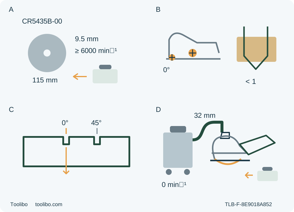
A · Match the original system
Actual CR5435B-00/01/22, original approved 115 mm/9.5 mm blade rated at least 6000 rpm and commissioned BY519702/QC536001 must match; remove pack for inspection.
B · Separate the two knobs
Battery out: motor-side depth knob and actual marks set through-cut with less than a full tooth. Front bevel knob separately locks zero.
C · Use the left zero notch
The left 0° notch belongs to this square cut; right 45° is not an alternative square reference. Verify the actual line on equally safe scrap.
D · Qualify extraction and grip
Already fitted native adapter and documented 32mm extraction must be active for cutting. Use only the actual documented main handle, with the free hand clear; conflicting physical instructions require manufacturer clarification.
Original conceptual isolated symbols are not to scale or a live operating pose. A does not authorize blade/ring fitting or a new battery system. B requires actual through-cut with less than a full tooth. C is an approximate sightline, not a factory offset. D depicts no auxiliary grip; the documented main-handle scope still requires a manufacturer hold if actual markings or supplied instructions conflict. The free hand never holds work or waste.
This is a complete modest square crosscut workflow for an existing US SKIL CR5435B-00 compact saw with the matching 01/22 manual. Its endpoint is a fully separated, measured wood sample—or a specific hold explaining why the actual system cannot be used. It does not commission a new battery, blade or extraction arrangement.
1. Resolve identity and grip before touching the task
Match the actual body, controls and supplied manual, not just the CR5435B-10 package name. The manufacturer’s current product identifies the included body as a one-hand circular saw; ordinary operating Figures 11–13 show its main-handle grip. This guide follows that exact model-specific ordinary operation. It does not invent an auxiliary handle or use the temporary guard-lever hand position illustrated for the excluded plunge operation.
There is an important qualification: the manual’s general symbol table includes an “always operate with two hands” symbol, introduced as symbols that may appear on the tool. This is not declared universally inapplicable. If the actual tool markings or supplied instructions conflict with the documented main-handle route, hold the task and obtain manufacturer clarification. Do not override a marking, improvise a second grip on the motor housing or let the free hand hold the work or waste. A compact body does not make a one-handed stock-holding cut acceptable.
Use only the actual already commissioned BY519702 / QC536001 system under its own complete instructions. Both identifiers appear in this tool’s listed power system; that does not qualify every 20 V pack or establish current carton contents. Missing power documentation, damage, modification or unexplained behaviour means hold. This article includes no charging, USB use, new-pair approval or indicator transfer from another SKIL tool.
2. Establish the original assembly and condition
The manual identifies a 4½-inch (115 mm) blade, 3/8-inch (9.5 mm) arbor and 6000 rpm motor. The retained original approved wood blade must be rated 6000 rpm or greater, with the correct original washers, bolt and any original assembly components already properly qualified. Do not round the bore to 10 mm or infer a ring conversion from the product’s accessory list. Blade thickness must not prevent the outer washer engaging the spindle correctly; clamping faces, blade direction and installed hardware must already comply with the complete instructions.
This is not a blade-fitting or tightening recipe. Incorrect, damaged, loose or unexplained assembly, an unidentifiable blade or a need for replacement requires qualified correction before cutting. The manual’s original combination blade covers wood crosscuts and rips, but this workflow uses only a square crosscut in known clean loose wood. Tile capacity, other blade types and the parts drawing do not expand that task.
Release the trigger, wait for complete standstill and switch OFF before battery removal. Press the release button at the front of the pack and pull it completely out. Inspect the accessible blade for dullness, damage, missing teeth, distortion or deposits without touching its teeth. Check the foot, handle, housing, trigger, lock-off and adjustment knobs for damage, looseness or unreliable action. A known faulty switch, bent foot, unusual vibration or uncertain contamination history is a service hold, never a reason for a powered diagnostic cut.
With the pack removed, use the actual retracting lever to check that the lower guard moves freely, closes instantly and has sound spring action. Verify no blade or other-part contact at all cutting angles and depths, including after a drop; then recheck the selected operating setting later. A slow or interfering guard must be serviced before use. Never tie or clamp it open. It operates automatically during this ordinary edge-entry cut.
3. Qualify material, environment and active extraction
Inspect the complete intended cut route for nails, screws and other foreign material. Choose dry, known clean wood approved for the original blade, not installed stock, a hidden-service area or material with unknown coating or treatment. Do not use ceramic tiles, metal, masonry, abrasive wheels, wet cutting, stacked pieces or an interior opening in this workflow. Keep the tool and workplace dry and exclude explosive or flammable liquid, gas or dust atmospheres.
Provide good light, balanced footing and a clear route without bystanders. Keep clothing, jewelry and hair away from moving parts. Use ANSI Z87.1 side-shield eye protection and a full face shield when needed, suitable hearing protection, ventilation and approved respiratory protection appropriate to microscopic dust and the actual exposure. The manual recommends tool operation at −10 to 40°C and storage at 0 to 40°C; these are not charging limits. Follow the power system’s own conditions separately.
The manual explicitly requires keeping the saw connected to suitable vacuum extraction during use. Its original dust outlet requires the supplied adapter for a 32 mm (1¼-inch) hose. This workflow assumes that exact native adapter is already correctly fitted and its actual hose and extractor are documented as suitable for the material. The parts list’s adapter identity is not installation permission or universal hose fit. If those prerequisites cannot be established, do not start.
Connect and check the hose with the saw OFF, fully stopped and battery out, and the extractor isolated under its instructions. Route it clear of the guard, cut, clamps and your grip from beginning to end. Then activate and check the extractor under its own instructions before cutting. A connected but switched-off hose is not active dust control. Neither the product’s blower listing nor a small blade replaces extraction, ventilation or respiratory protection; no unverified pressure or airflow number is supplied here.
4. Plan a crosscut that remains supported at the exit
Use a specimen large enough to be securely clamped and to support the actual foot throughout the operation. Mark a square line from a reliable edge, identify the retained portion and waste, and establish the desired finished dimension and acceptable edge quality. Place the appearance face down as the manual directs, without promising a splinter-free result.
Clamp the retained work to a stable platform. Support both portions near the cut and edges outside the blade path. The source depicts broad faces of support timbers, not narrow-edge balancing. Waste remains independently supported but free to separate without closing the kerf. No hand may support either piece during cutting; no clamp may trap the future kerf. Plan where the fully stopped, guarded saw can be set down without contacting your body or displacing the work.
The product identifies a left-blade body. Keep the broader retained-side foot support available and assess the actual full footprint rather than copying another saw’s guide offset. This square crosscut uses the marked line and actual zero sightline; optional rip-fence fitting and the right-foot board-guide rip are not necessary to complete it and are not taught here.
With the battery removed, assess reach and all clearances beside or safely above the proposed path, blade guarded and teeth clear. Do not push a projected blade through uncut stock or force the guard open as a rehearsal. The main-handle grip must remain controlled, the free hand clear, and the hose must not tug or snag at the exit. If the actual layout cannot achieve that, hold or choose a different qualified work arrangement before cutting—not halfway through a live cut.
5. Set the depth knob, front bevel knob and left notch
Keep the pack out. The depth-lock knob is beside the motor housing. Loosen it, hold the foot flat against the workpiece edge and raise or lower the saw by the handle. Align the depth indicator on the bracket with the chosen depth-of-cut mark on the upper guard, then tighten the knob securely. Verify the actual blade reaches through the wood without reaching the table or supports.
The safety section requires less than a full tooth visible below the work. Later adjustment wording permits no more than one tooth; use the stricter partial-tooth condition, not a full-tooth drawing or a guessed millimetre conversion. Both through-cut and support clearance must hold. Nominal maximum depth does not prove that a particular specimen can meet these conditions.
Separately loosen the front bevel-lock knob, set the actual indicator to zero on its bracket and retighten. Confirm both depth and bevel remain secure and the intended square relationship is established. This guide does not adjust calibration screws or teach bevel cutting. Failure to lock or uncertainty about alignment needs qualified correction, not forced steering.
For a zero-degree square cut use the left notch. The right notch is the 45-degree reference. They are approximate sightlines, so verify the real cut line on equally well-supported safe scrap before committing valuable material. A change of blade, angle or reference arrangement invalidates an old offset assumption.
6. Start, feed and stop under the actual control sequence
Before inserting the pack, check trigger return to OFF and lock-off action in isolation, remove setup tools and reconfirm clamping, settings and extraction clearance. With the tool OFF, align the actual pack’s raised ribs with the tool grooves and slide it in until the latch snaps correctly; confirm secure retention without forcing. Never attach power to investigate a suspect control.
Grip the actual main handle firmly on its insulated gripping surface, as in the model’s ordinary operating figures. Position your body beside the blade line and prepare to resist the tool’s reaction. Keep the other hand away from the cutting area, underside, guard and waste—it does not steady the stock. The front of the foot must be supported on retained material with the blade clear before start.
Press and hold lock-off with your thumb, squeeze the trigger with your finger, then release lock-off while maintaining the trigger. Let the blade reach full speed before contact. Keep the foot flat and feed straight forward with light continuous pressure. Let the lower guard operate automatically. Do not force, twist, pulse the switch or reach for a moving offcut.
After normal complete separation, release the trigger and maintain control until the blade actually stops. Confirm the lower guard covers it before lifting or setting down, without brushing your leg or clothing. Remove the pack before inspecting the pieces or altering the fixture. There is no safe-stop countdown: the product’s brake listing and the LED’s approximate ten-second afterglow do not establish standstill.
If the blade binds or cutting is interrupted for any reason, release the trigger immediately and hold the saw motionless until fully stopped. Do not pull backwards or withdraw a moving blade. Isolate before investigating. This guide does not teach restarting in an old kerf, repeated protection resets or extraction of a trapped tool.
7. Inspect the result and retain useful evidence
Battery out, check complete separation, the finished dimension from the reference edge, squareness across width and thickness, and tearing, scorch or roughness on both faces. Also inspect the process: settings and clamps stayed fixed, the foot remained supported, waste separated freely, the free hand stayed clear and extraction remained active without hose interference. A dimensionally acceptable piece does not cancel a failed safety condition. Do not handhold a small failed piece for a corrective recut.
The LED behind the upper guard illuminates during running. Rapid flashing accompanies overload or excessive temperature with internal shutdown; slower flashing indicates low charge. Record unexpected signals or loss of speed, stop and follow the matched instructions or qualified service route. Do not turn these indications into a guessed electrical diagnosis, a live protection test or an automatic return-to-use decision.
Remove the battery for cleaning and storage. Keep accessible guard, ventilation and switch areas clear without inserting pointed objects or introducing liquids. Store indoors away from children and corrosive agents, with the separate battery safely protected from terminal shorting under its own instructions. Blade removal, solvent cleaning, sharpening and internal maintenance are excluded. A useful service handoff records actual model/manual, original assembly identity, power pair, material, settings and observed symptoms without reproducing them under power.
Models referenced