
Two-pack isolation and model-specific setup
A shows two detached 5 Ah packs and empty mounts. B highlights the depth lever bottom contour and large zero versus small 45-degree notch. C qualifies the original 184/16 mm blade rated at least 5,300 rpm and stationary guard coverage. D shows isolated upward travel, blade left, guide right and the 32 mm auxiliary-handle hose with neutral grip contacts.
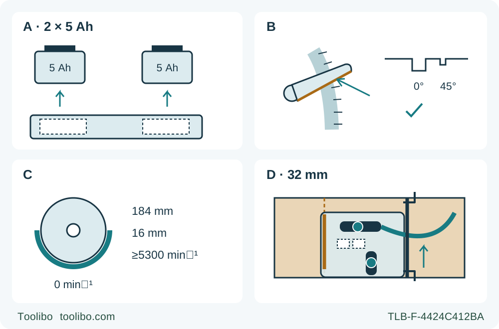
A · Remove both packs
Confirm both actual BY519603 5 Ah packs are detached before any setup; no smaller-pack substitution.
B · Read the bottom contour
Align the lower contour with the bracket, secure depth and zero bevel, and use the large zero notch.
C · Keep the qualified assembly
Use the already correct original 184/16 mm wood assembly and at least 5,300 rpm blade rating; wait for stop and guard coverage.
D · Rehearse the right-side guide
With both packs absent, guide the right foot edge and confirm both grips, retained support and 32 mm hose clearance.
All setup and D rehearsal have BOTH packs removed. B uses the lower contour, not lever tip, and actual depth remains less than a full tooth below the work. C is original-assembly qualification, not a replacement procedure. D is a conceptual stationary plan: upward travel, operator-left blade and right foot edge against the guide, with the hose clear of the guard. No panel depicts charger operation; charging is outside this already-commissioned owner workflow.
The SKIL CR5429B-00 rear-handle saw uses two battery packs together. That changes a basic setup habit: removing one pack because the motor will no longer run is not the prescribed isolation procedure. Both packs come off before inspection, adjustment, accessory work, cleaning and storage. This guide builds a complete supported square-cut task around that two-pack rule, the depth lever’s bottom contour and the right-hand edge of the foot.
The scope is the actual US CR5429B-00 with the current product-linked tool manual, an original correctly fitted wood blade and two genuine BY519603 5 Ah packs already commissioned under the owner’s complete system instructions. The current CR5429B-20 product identifies that body, those two packs and QC5359B-02, but this does not promise the contents of another carton or establish a new charging procedure. Match the labels on the actual equipment and read its full instructions before working.
Establish the two-pack boundary before handling the saw
The tool is rated 40 V from two 20 V packs and does not work with only one. The current manufacturer product explicitly requires 5 Ah or higher, while the older tool table includes smaller capacities. This workflow deliberately uses only the two actual BY519603 5 Ah packs. Do not use the broad table or related-product tiles to authorize 2 Ah or 4 Ah substitutions, and do not treat a nominal 40 V pack as interchangeable with the two specified 20 V packs.
There is also a chronology limit in the documents. The battery manual dated 01/19 lists SC535801 and QC536001 chargers; the later tool table and current product name QC5359B-02. The old battery table does not reciprocally establish that later charger. The current product is explicit pairing evidence, but complete current charger instructions and their actual display details have not been established here sufficiently for a charging tutorial. Therefore, this is only for an owner whose actual approved system is already commissioned and whose complete supplied instructions resolve its use. If that prerequisite is missing or unclear, stop for manufacturer confirmation rather than trying a charge cycle from this article.
Both packs must be undamaged, ready for use and already charged under those instructions, including the required first full charge before first use. There are no charger connections, mains ratings, charge-time promises or charger light tables in this workflow. Do not use damaged, modified, dropped or sharply impacted packs. Protect detached terminals from loose metal objects; do not leave packs outdoors, in vehicles or stored on a charger.
Switch the saw off before attaching or removing either pack. To isolate it, press a pack’s release button and slide it out, then repeat for the second pack. Visually confirm that both mounting positions are empty. This remains the routine even though one missing pack prevents normal operation. A lock-off button or protection shutdown is not the two-pack removal step.
Qualify the existing blade and automatic guard
With both packs removed, identify the original 7¼ in / 184 mm wood blade and 5/8 in / 16 mm arbor arrangement. The blade must be rated at least 5,300 rpm. It must be suitable for the selected wood and already correctly installed with the original washers and bolt. The outer washer must properly engage the spindle flats, and the washer clamping surfaces must be clean, flush and correctly oriented. Unknown assembly history, damaged teeth, excessive thickness, a bent blade or uncertain hardware means the task stops.
The full manual has a model-specific blade-fitting procedure, but this guide does not reproduce part of it. Do not loosen the bolt to check it, borrow another saw’s tightening method, use a longer wrench or modify an arbor opening with the supplied wrench’s wedge feature. If fitting or correction is needed, return to the complete matched procedure or qualified assistance. Metal, masonry and abrasive wheels are excluded; their debris can interfere with the guard. The sample is known untreated wood only.
Check that the lower guard moves freely and returns immediately. Use its retracting handle for the isolated check, keep fingers clear of teeth and confirm that it cannot contact the blade or other parts at all angles and depths of cut. A damaged spring, sluggish return or bent guard needs service before use. After a drop, check all angles and depths. Do not clamp the guard open: this ordinary edge-start cut relies on its automatic movement.
Inspect the foot, both handles and the switches for damage, looseness or binding. The main rear handle and auxiliary front handle must both remain available during the cut. If the blade wrench is stored on the tool, it must have the illustrated correct orientation and be fully seated at its second lock detent; an incorrectly stored wrench can damage the workpiece. This is a storage check, not permission to use it for an improvised adjustment.
Use the bottom contour to set actual depth
Keep both packs off. Raise the depth-adjustment lever to loosen it, hold the foot flat against the work’s edge and raise or lower the saw with the main handle. Align the bottom contour of the lever, not its tip, with the desired mark on the calibrated bracket, then tighten the lever. Check that the setting cannot move.
The bracket’s standard-lumber references are a shortcut to an initial position, not proof of the actual blade projection. The adjustment illustration describes a one-tooth boundary, while the safety section requires less than a full tooth below the work. For this sample, physically verify less than one full tooth visible beneath the actual wood, with enough depth to cut through. Do not leave excessive blade exposed simply because a nominal lumber label appears on the bracket.
Loosen the front bevel-adjustment lever, align the indicator with zero on the quadrant and retighten. The manual’s isolated 90-degree check uses the foot at maximum depth and a square between the blade and foot; avoid the teeth and return to the sample’s correct depth afterward. If the square check fails, stop for the complete documented alignment procedure or service. This article does not teach the separate alignment screw or the over-45-degree stop-spring procedure.
Use the large foot notch for the square cut. The smaller notch is the 45-degree reference, not another zero reference. Both are approximate sighting aids: an actual scrap cut is needed because blade type and thickness affect the real kerf. Mark the retained dimension and waste side before positioning a guide, then confirm the offset on the sample rather than cutting directly to a finished part’s line.
Support the cut and guide the right edge of the foot
Choose a manageable piece of dry, flat, untreated wood without hidden fasteners. Clamp it to stable support; neither hand should hold the stock. Large sheets need support on both sides near the cut and near the sheet edges, without placing any support in the blade’s path. Where support lumber is used, the manual specifies its wide faces against both the work and the bench, not an unstable narrow-edge arrangement. No load rating or universal support spacing is assumed here.
Keep the broad foot supported on the retained piece through the final separation. Arrange the offcut so its weight will not close the kerf, twist the blade or pull the work off the supports. A setup that needs someone to catch the offcut or a hand beneath the blade is not ready.
For this guided sample, clamp a straight piece of 1 in / 25 mm lumber as the board guide described in Figure 16. Run the right side of the foot against it. Establish the actual contact-edge-to-kerf offset with the installed blade; do not copy a dimension from another saw. The separate rip fence is an accessory, not a promised included part, and no fence may interfere with the guard or blade. This task uses the clamped board instead.
The source’s operating perspective confirms an operator-left blade. In an upward-travel planning view, the blade and cut are left, the broad retained base and board guide right. That describes the tool geometry, not a command to place the body in the blade line. Stand to the side with stable footing and use both grips.
Prepare eye protection marked ANSI Z87.1, hearing protection, suitable respiratory protection and ventilation. For the selected dusty wood operation, connect suitable extraction through the 32 mm / 1¼ in port at the auxiliary handle using the correct hose or adapter. Route the hose so it cannot obstruct the lower guard, pull the front grip or snag a clamp. No vacuum performance value from another model is imported here.
Rehearse the full travel with both battery positions still empty. The foot should remain flat against the guide, the guard free, the hose slack enough for the whole cut and the clamps clear of the motor and foot. Keep the hook folded; it is not a support handle or a place to attach body weight. This sample does not use suspended storage or hook-based support.
Install both ready packs only after the checks pass
With the switch off and fingers clear of the trigger, align the first pack’s ribs with its mounting grooves and slide it into place until its latch engages. Repeat with the second pack and verify both are secure. Do not force a misaligned pack. A failure to start with one or both positions uncertain is a reason to switch off, remove both and inspect, not to hold a pack in by hand.
Place the foot at the entry edge with the blade clear of the wood. Hold the rear and auxiliary handles, press and hold the lock-off with the thumb, then squeeze the trigger. The lock-off can be released while the trigger remains held. Let the saw reach full speed before advancing. Guide it with steady pressure and keep the foot flat; do not force, twist or cycle the switch while cutting.
For normal completion, finish the cut before releasing the trigger, while maintaining support and control. Then wait for the blade to stop completely and the lower guard to cover it before lifting away or setting the saw down. The product’s electric-brake feature does not supply a universal stopping time. Keep the saw away from a leg or clothing while the blade is coasting.
Binding or an interruption is different from normal completion: release the trigger immediately and hold the saw motionless until it stops. Never pull a rotating blade backward out of the kerf. Switch off and remove both packs before investigating support, alignment or blade condition. Resolve the cause rather than repeatedly restarting a stalled cut.
The tool’s own LED can flash rapidly for overload or heat and more slowly for low pack capacity; these are not charger-light meanings. A shutdown or warning is not a successful cut or physical isolation. Stop, remove both packs and follow the actual tool and pack instructions for the cause. Do not bypass protection, force another pass or confuse the tool light with a complete battery-system diagnostic.
Accept the sample and leave the system isolated
After standstill, guard closure and removal of both packs, measure the retained dimension in several places and check squareness and straightness. Look for burning, torn fibers, variable kerf width or guide movement. Also assess whether the stock stayed stable, the foot remained supported and the hose remained clear. A correctly sized sample is not acceptable if the process bound or rocked.
Correct any cause while isolated and repeat on scrap before committing the intended workpiece. A dull or contaminated blade needing removal belongs with the complete matched maintenance instructions; this article does not provide a partial chemical-cleaning or sharpening recipe. Keep the guard, vents and switch areas clean without inserting pointed objects or exposing plastics to damaging solvents. Store indoors away from children and corrosive agents, with both packs removed and their terminals protected. The repeatable outcome is a verified two-pack-isolated setup and a stable square cut, not a newly commissioned charger or replacement blade system.
Models referenced