
Identity, isolated controls, exact charging pair and stationary rehearsal
Four panels show a 140 by 10 mm blade rated at least 4,200 rpm; removed battery with lock-off then trigger recognition and less than one tooth; BY519801 4 Ah with QC535701 120 V/60 Hz normal charging; and a stationary supported blade-left square-cut layout with neutral grip dots.
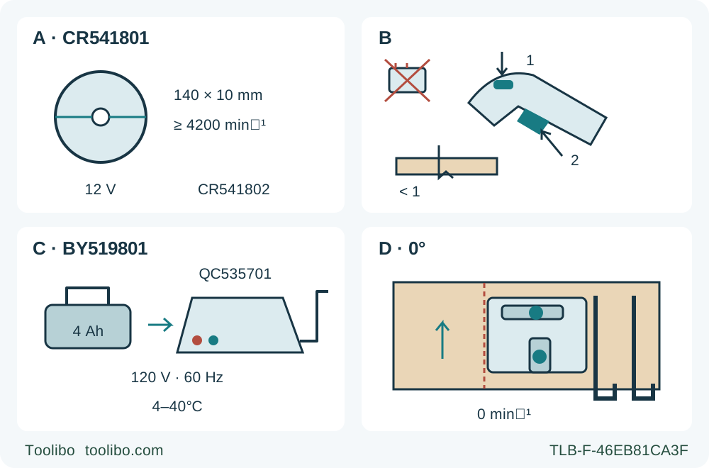
A · Exact original assembly
Confirm CR541801, 12 V and the original matched 140 mm / 10 mm wood blade rated at least 4,200 rpm; a related listing does not establish fit.
B · Isolate and recognize controls
Remove the pack for setup. The lock-off precedes the trigger during operation; securely lock depth with less than a full tooth below the wood.
C · Actual charging pair
Use owner-labelled BY519801 4 Ah and QC535701 on 120 V/60 Hz; normal-charge green flashes then stays green, while steady red requires pack removal.
D · Stationary supported rehearsal
With the battery removed, check clamps, retained-side foot support, both grips and hose clearance before a square sample.
A identifies the body and related CR541802 offer, not a carton promise. B is disconnected control recognition: 1 marks the lock-off, 2 the trigger, and <1 means less than one full tooth below the stock; it is not a powered test or blade-fitting procedure. C shows separate indicator colours, not simultaneous charging/fault states, and 4–40°C is the normal-charge range. D is battery-removed, stationary rehearsal with upward intended travel, cut left and broad support right; dots identify two grip contacts, not body position. Follow the text’s left-of-blade body placement.
Match the saw body, battery and charger separately
The operating identity in the saw manual is SKIL CR541801. The current US CR541802 product page links the manual bundle containing that body’s instructions. Treat the two numbers as a body-and-offer relationship, not two different saws or proof that every seller supplies the same carton. This workflow is for an existing CR541801 owner whose actual labels read BY519801 on the 4 Ah battery and QC535701 on the charger.
The three manuals establish that exact combination: the saw lists both items, the battery approves the charger, and the charger lists the battery. Read all three, not just the saw’s start-up page. The freshly checked documents are the saw’s 03/19 instructions, the individually linked BY519801 manual with 12/18 footer and the individually linked QC535701 manual with 07/19 footer. The individual battery and charger downloads are not assumed byte-identical to copies inside the saw’s ZIP bundle.
The outcome is a fully qualified power system and a supported square sample in known untreated wood, followed by an inspection of the cut and safe storage. This is not a new-kit guarantee, a blade-replacement tutorial, a plunge-cut lesson or permission to fit any battery bearing a 12 V label.
Qualify the original blade and the isolated tool
Remove the battery before assembly, adjustment, cleaning, carrying the saw at your side or leaving it unused. A released trigger and its lock-off button are not equivalent to removing the pack. Keep a detached battery away from loose metal that could bridge its terminals.
Begin with the original, correctly installed, suitable wood blade and matching mounting parts. The manual specifies 140 mm diameter, a 10 mm arbor and a blade speed rating of at least 4,200 rpm. The source’s imperial arbor shorthand must not be used to substitute a 9.5 mm bore or another model’s blade. A current product-table alternative-size entry is not used to broaden this original-assembly workflow. A related-products blade listing is also not proof of fit.
The CR541801 assembly instructions are model-specific: they describe clockwise bolt removal and a defined final tightening increment after finger-tightening. Those are not generic SKIL rules. This guide intentionally does not extract those details into a partial fitting sequence. If the blade, washers, bolt, direction or assembly history is uncertain, stop and use the complete matched instructions or authorized service. Do not use abrasive wheels, an improvised adapter or a blade so thick that the outer washer cannot engage correctly.
With the battery out, inspect the foot, handles, guard, controls and visible fasteners. The lower guard must move freely and close immediately at all angles and depths of cut without contacting the blade or other parts. A sticky guard, damaged spring or bent foot requires correction before use. Never tie the guard back. For the ordinary edge-start cut below, let it operate automatically.
Prepare the exact charging station
The QC535701 input is 120 V, 60 Hz AC, 90 W. Match the actual charger label and outlet; do not interpret a generic extension-cord table as permission to connect this charger directly to another mains voltage. Use it indoors in a dry location on a flat, nonflammable surface with ventilation. Keep it away from heat and flammables, and route its cord away from feet and damaging edges. Avoid an extension unless absolutely necessary and properly qualified by the charger instructions.
Inspect the charger housing, cord, plug and battery case. Do not charge a cracked, damaged, modified or seriously impacted pack. Do not open either enclosure. Smoke, melting or damage ends use and requires the appropriate service response, not repeated charging attempts. Unplug the charger before cleaning or storage.
Normal charging is specified for a battery temperature of 4–40°C; PWRJUMP has a separate 10–40°C range. Storage is 0–40°C. These are different limits, not a single temperature range to apply to every activity. This workflow uses normal charging. Fully charge the pack before its first use; a partly charged new battery is not an exception.
Connect the charger to the correct supply. Its indicators briefly illuminate for self-inspection and then go out. Align the battery ribs with the slot and insert the pack fully without forcing it. The charger evaluates the pack and begins the appropriate charging process. If normal charging does not start, read the actual indicators rather than assuming that an unlit lamp means “finished.”
Read the charger lights, not the saw light
During normal charging, the green normal-charge indicator flashes. When charging is complete, that indicator stays green. The PWRJUMP indicator is a separate lamp and may remain off when that function is not used. Do not combine the lamps into one invented status signal.
A steady red defect indicator identifies a hot or cold battery condition. Remove the battery from the charger. Let a hot pack cool with airflow, or let a cold pack reach room temperature indoors, before reassessing it within the specified range. The source table expressly says to remove it; this is not a leave-it-docked thermal-retry instruction borrowed from another charger.
A flashing red defect indication calls for the manual’s fault process, not more pressure on the pack. For an otherwise undamaged pack, the manual allows removal and reinsertion once. If the fault repeats, stop treating that pair as ready and arrange authorized diagnosis; do not open the pack or charger or keep cycling it indefinitely. No response during charger self-check also needs supply/connection checks and service if unresolved, rather than being counted as a successful charge.
The advertised five-minute PWRJUMP example concerns a depleted 2 Ah battery reaching approximately 25%, not a measured promise for this 4 Ah BY519801. Do not halve, double or transfer that result to calculate a guaranteed charge time. Remove the battery when charging is complete and do not store it in the charger. The battery’s USB port must not power another device while the battery itself is charging.
Set a square cut with the pack removed
Use a sufficiently large, dry, untreated wooden sample, inspected for nails and other foreign objects. Secure it with clamps on stable support near the cut, leaving the blade path clear below. Larger panels need support on both sides near the cut and near their outer edges so that sagging does not close the kerf. Keep the foot on the supported retained section, not on the offcut. If you would need a free hand to hold the work, redesign the setup.
With the pack still out, loosen the depth lever, set the foot and saw to the required depth, then lock the lever securely. The operating section says no more than one tooth length below the wood, while the safety section requires less than a full tooth. Use the stricter less-than-one-full-tooth boundary and inspect the actual projection. Do not leave maximum depth selected merely because the board is thin enough to cut through.
Set zero bevel and securely tighten the bevel-adjustment knob. The tool’s 0–50° range does not make this a bevel-cutting exercise. At an angle, the depth gauge no longer directly represents the resulting depth, so a square-cut setting must not be carried unchanged into an unrelated bevel task.
For zero degrees, use the left notch marked 0° in the saw-line window. The right notch marked 45° belongs to that bevel angle. These are approximate references: a disposable sample establishes the actual kerf and offset for the installed blade. Mark the retained boundary and waste side. For a long rip, clamp a suitable straightedge, keeping its clamps clear of the housing and verifying the actual base-to-cut offset instead of relying on the manual’s approximate base-width figures.
Check extraction, grip and the complete travel
The saw has a 1-1/4 in vacuum extension. Connect a suitable extraction hose or the necessary compatible adapter, and check that it never interferes with the lower guard or the cut. A hose that fits the port can still be badly routed. Arrange suitable dust extraction, ventilation, eye and hearing protection and respiratory precautions for the wood; avoid unknown coatings or treated/reclaimed material in this sample.
Rehearse the layout with the battery removed and the blade stationary. Check the supported foot, guide contact, clamp clearance, hose slack and room to finish. Keep both hands available for the main and auxiliary handles. The operating instructions position the body to the left of the blade, with the cut to the side rather than directly in line with the body. Do not confuse which side supports the broad foot with where the operator should stand.
The diagram’s D panel is an isolated, stationary rehearsal. Its upward arrow gives the intended travel direction, with the left-side blade and broad supported foot to the right. The two dots identify grip contacts only; they are not directional forearms or an instruction to stand on the supported-board side. No hand holds the stock or reaches underneath it.
Start deliberately and distinguish tool indications
Check the battery gauge before fitting the pack: press its indicator button to display the capacity lights; the first LED flashes green when charge is low. That gauge is separate from both the charger display and the saw’s work light. Fit the pack only when setup is complete and the trigger is released. Align the ribs and grooves, slide it into place and verify that the latch has secured it.
Rest the front of the foot on the work with the blade clear. Push the lock-off button before pulling the trigger. The work light can illuminate with a light trigger squeeze before the motor starts and can remain on for 8–12 seconds after release. It is not a reason to use the tool in an inadequately lit work area, nor proof that the saw is disconnected.
Rapid flashing of the saw light indicates overload; the tool and/or pack can shut down when overloaded or too hot. Stop, remove the pack after standstill and let the tool and battery rest separately with airflow if needed. Slow flashing indicates low battery capacity and calls for recharging. Do not read these saw-light patterns as the charger’s red/green fault codes or repeatedly restart against an unresolved load problem.
Make and accept the sample
Hold both handles, let the blade reach full speed and advance with light, continuous forward pressure. Keep the foot flat and the supported retained section under it. Do not force the saw, twist it back toward a missed line or move a hand onto the workpiece. At the finish, release the trigger and wait for the blade to stop completely before lifting the saw. Confirm lower-guard closure before setting it down. No advertised brake feature supplies a guaranteed stopping time or removes these checks.
If the blade binds or a cut is interrupted, release the trigger and hold the saw motionless until the blade stops. Do not pull a moving blade backward. Remove the pack before finding and correcting the cause. A shifted support, damaged blade, unreliable lock or repeated vibration rejects the setup even if the cut looks nearly straight.
With the tool stopped and isolated, check the sample’s finished dimension, straightness and square edge. Adjust the guide only while isolated and repeat a sample after a relevant change. Keep accessible vents and guard areas clean without inserting pointed objects or improvising solvent cleaning. Remove the pack for storage, protect its terminals from metal objects and unplug the empty charger. Record the accepted blade, stock, depth and guide arrangement so the next cut begins with a known setup rather than a remembered marketing claim.
Models referenced