
Single-pack isolation, charging and reference checks
Four diagrams show a detached labelled BY519701 pack, separate SC535801 charging and hot-cold indications, left zero and right 45-degree notches, and a hose clear of the lower guard.
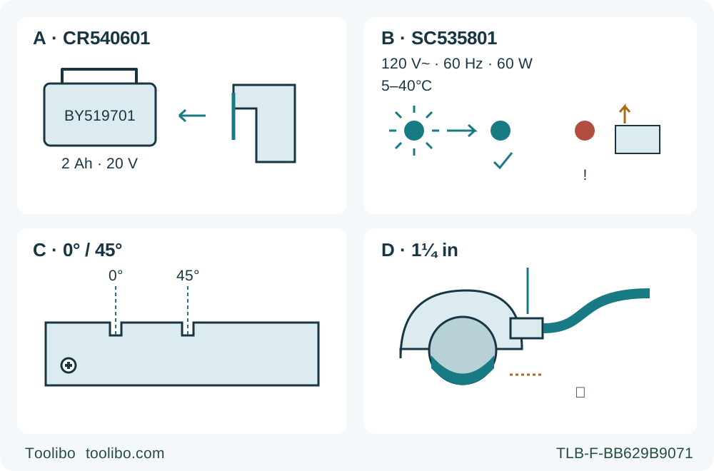
A · One detached pack
Remove the BY519701 before adjustment and carry; the lock-off and released trigger are not power isolation.
B · SC535801 charging
Use the labelled 120 V AC/60 Hz supply and 5–40°C charging range; fully charge before first use and remove a hot/cold pack on steady red.
C · Approximate cut references
Use the left 0° notch for the square sample and verify the actual line on scrap; the right notch is 45°.
D · Guard clearance
Connect suitable extraction at the 1¼ in port and route the hose so it cannot interfere with guard movement or cutting.
A controls checklist, not a live cutting pose or kit-content promise. A requires the owner’s actual component labels to match. B shows alternative states: flashing green charging, steady green complete, or steady red requiring pack removal for temperature recovery; they are not simultaneous lights. C uses the manual’s left 0° and right 45° references. D keeps the hose away from the lower guard; it does not depict a powered extractor inside the saw.
Build one complete single-pack wood-cutting setup
This guide takes an existing SKIL CR540601 from a verified battery-and-charger combination through an isolated mechanical check to a supported square wood sample. The important distinctions are the single removable pack, the ordinary depth indicator beside the main handle, the left 0° and right 45° saw-line notches, and the separate meanings of charger, battery and saw lights. A familiar green light is not enough to identify which part of the system is ready.
The operating source is the CR540601 manual with a 01/21 footer, currently linked from SKIL’s owners index and CR540602 product page. The CR540602 listing is a kit presentation, not another saw body for this workflow. Here the owner must actually have a BY519701 2 Ah battery and SC535801 charger, with labels matching the three manuals. Those exact components are expressly compatible in the saw, battery and charger documentation. This is not a promise that every carton labelled CR540602 contains those precise accessory model numbers, nor permission to substitute an arbitrary 20 V pack. Read all three complete manuals before use.
Remove the battery before qualifying the installed blade
The saw is capable of starting whenever a pack is attached. Remove the battery before adjustments, assembly checks, cleaning, storage and carrying the tool at your side. Press the release button and slide the pack fully away; merely releasing the trigger or relying on the lock-off button is not isolation. Keep the detached pack’s terminals away from screws, keys and other metal objects.
This article starts with an original, correctly installed wood-cutting assembly. The saw specification is a 6½ in (165 mm) blade with a 5/8 in arbor, shown as 16 mm in the manual, and 4,500 rpm no-load speed. The blade must be rated at least 4,500 rpm and must not be so thick that the outer washer cannot engage the spindle’s flat. The correct washers must be clean, face the blade and sit flush, with the blade’s rotation matching the guard marking. These are prerequisites, not an abbreviated fitting tutorial.
If blade identity, seating, washer arrangement, fastening or guard condition is uncertain, stop and resolve the complete installation through the exact instructions or authorized service. Do not prove a questionable assembly by running it. This saw is for wood only: exclude metal, masonry, abrasive wheels and unknown installed materials. The spindle lock is used only at standstill, never as a brake.
Charge the named pack before first use
The SC535801 documented input is 120 V AC, 60 Hz, 60 W. Match its actual label and supply; a general extension-cord chart elsewhere in the booklet does not turn it into a universal-voltage charger. Inspect charger, cord, plug and pack before use. Do not charge a cracked, damaged, modified or impact-damaged pack, and do not open either device for repair. Use the charger indoors, dry, on a flat nonflammable surface away from combustible materials, with unobstructed ventilation. Avoid an extension cord unless absolutely necessary and then follow the exact charger requirements.
The specified charging temperature range is 5–40°C; recommended storage is 0–40°C. A new pack arrives partly charged: fully charge it before first use. It does not need to be deliberately exhausted before later recharging.
Connect the empty charger to the supply. Its red defect and green charging indicators light for one second, then go out, indicating the self-check has completed. Align the pack ribs with the charger slot and slide it into place without force. A flashing green light means charging; steady green means fully charged. Remove the charged pack and unplug the charger when finished. Do not use the charger as a storage dock or leave the pack there beyond the manual’s recommended 24-hour limit.
Steady red is the hot/cold indication, not a command to leave the pack in place indefinitely. Remove it from the charger. Let a hot pack cool under airflow, or bring a cold pack indoors until it reaches room temperature, before another attempt within the permitted range. Do not immerse it or apply improvised heating.
A flashing red defect light can indicate a pack problem or poor connection. The manual permits removing and reinserting the pack; if the indication returns, stop this single-pack workflow and seek authorized SKIL diagnosis. The manual’s further comparison with another known compatible pack is not a reason to buy a spare or use an unidentified battery for testing. If the empty charger’s self-check never occurs, verify the supply as instructed and have persistent failure serviced. No light should be treated as proof of charging success.
Keep the three indication systems separate
The BY519701 has its own four-light gauge, read by pressing the battery-indicator button. The first light flashing slowly indicates low charge. The first and third lights flashing rapidly green indicate a pack that is too hot; let it cool under airflow. These are pack-gauge patterns, not the SC535801 red/green charger legend.
The saw’s LED is behind the upper guard. It turns on when the trigger is pressed and off when the trigger is released; this manual does not specify a ten-second afterglow. Rapid flashing accompanies an overload or excessive tool/pack temperature and protective shutdown. Release the trigger, wait for complete blade standstill and remove the pack before inspecting the cause. Rest the tool and cool tool and pack separately under airflow when needed. Resolve excessive feed, binding or other causes before another attempt; protection is not permission to keep forcing the cut, and a stopped motor is not physical isolation.
Support known wood and verify the lower guard
Choose a sufficiently large, flat sample of known untreated wood suitable for the installed blade. Check for fasteners and other foreign objects. Exclude tiny hand-held pieces, hidden services, hazardous coatings and internal plunge cuts. Clamp the sample to a stable platform, with support near the cut and enough clear space underneath for the blade. Large panels need support on both sides near the cutting line and near their edges. Arrange the offcut so that it cannot drop into the blade or close the kerf.
Keep the saw’s foot on the supported retained portion, not on the offcut. Never hold stock with the free hand or across a leg. Plan a stable stance beside the blade line and two-handed control using the main and auxiliary handles. Wear appropriate eye, hearing and respiratory protection, provide ventilation and suitable source extraction, and keep people away from the cutting and dust area.
With the battery detached, use the lower-guard lift lever to check free movement and immediate closure. Check that the guard and spring work properly and that the guard does not touch the blade or another part at all angles and depths of cut. Do not tie it back. A sluggish or damaged guard must be corrected before use. For this ordinary edge-start cut, let the workpiece operate the guard normally.
Set depth, zero bevel and the correct window notch
The depth-adjustment lever is beside the main handle. With the battery removed, loosen it, hold the foot flat against the workpiece edge and raise or lower the saw until the indicator aligns with the intended depth on the gauge. Tighten the lever securely, then check the actual tooth projection. The setting note says not more than one tooth; the general safety requirement says less than a full tooth. Use less than one full tooth below the sample, and confirm the lock holds. Do not import the bottom-contour reading rule from a different SKIL saw.
For the square sample, loosen the bevel knob counterclockwise, set zero and tighten clockwise. Check the blade-to-foot square relationship without touching the teeth. The 0–50° adjustment range is not a claim that the 45° cutting capacity applies at 50°. Nor does the normal depth-gauge reading remain the actual cutting depth at an angle. Bevel cutting and stop-screw calibration are outside this first square-cut workflow; an inaccurate or unstable zero needs correction before proceeding.
Use the left notch at the 0° indicator for a square cut. The right notch is the 45° reference. The saw-line window is only an approximate cut-line aid, so prove the actual line on scrap. Do not loosen its adjustment screw merely to conceal a bent base, a loose setting or a wrong guide offset. If reducing top-face tear-out matters, the manual advises placing the good face down, while still maintaining safe support and an appropriate blade.
Connect extraction and clamp the straightedge
The extension behind the upper guard is a 1¼ in vacuum connection. It is a port, not a powered extractor built into the saw. Connect a suitable vacuum hose, using a suitable adapter if necessary, and check the real fit. The hose must never interfere with the lower guard or cutting operation. Support it so it cannot drag the saw sideways or snag a clamp.
Use a rip fence or straightedge for ripping, especially long or wide cuts. This workflow uses a straightedge clamped to the sample. Position its clamps clear of the saw housing, foot and hose. Measure and trial the actual blade-to-guide offset instead of treating the manual’s approximate left/right base dimensions as a finished-cut setting. The rip fence is described as included with some models; do not assume it came in every package.
With the pack still removed and blade clear, rehearse the route. Confirm the guide is secure, the foot remains supported, both grips stay available, and neither hand or hose obstructs the guard. If any condition fails, correct it before installing the battery.
Make the sample and accept the whole setup
When ready, align the charged pack’s rib with the saw’s groove and slide it in until the latch snaps securely. Keep the trigger released while doing so. Rest the front of the foot on the workpiece with the blade clear. Hold the main and auxiliary handles, press the lock-off button and pull the trigger. Wait for full speed, then feed smoothly along the guide without forcing or twisting.
At the end, release the trigger and allow complete blade standstill before lifting the saw. Verify the lower guard is closed before setting the tool down; do not let the saw brush your leg or clothing during coast-down. For binding or any interruption, release the trigger and hold the saw motionless in the material until stopped. Never pull backwards or lift out with a moving blade. Remove the pack before investigating a closing kerf, shifted clamp, dull blade or loose setting. This guide does not teach a hurried restart in a jam.
After removing the battery, check dimension, squareness, burning or excessive tearing, and confirm the depth lever, bevel knob and guide stayed secure. An unusual vibration, slipping blade, damaged base or unreliable switch rejects the setup even if the cut looks acceptable. Have uncertain assemblies or defects corrected through the complete manual and authorized service, rather than compensating with more feed force.
Clean only with the tool isolated and charger unplugged; keep vents and controls free of debris without inserting pointed objects. This article does not provide solvent blade-cleaning or internal repair instructions. Store the saw and pack indoors, dry and inaccessible to children, with protected terminals and no corrosive agents. The final outcome is a verified single-pack square-cut system, including charging and stopping decisions—not a new kit identity or permission to transfer another model’s controls.
Models referenced