
Four original-system recognition checks
A identifies PCL500 and original 140mm assembly. B separates rear depth knob and front bevel knob with detached battery. C shows partial tooth and quarter-inch ceiling. D marks actual two gripping points and a complete connected extractor.
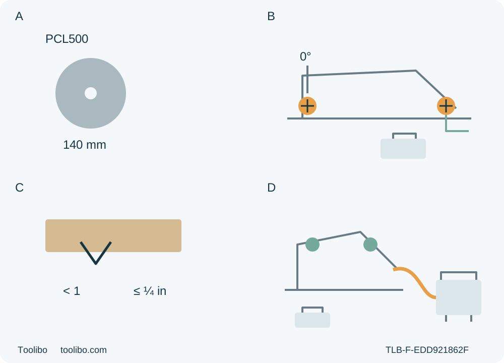
A · Qualify the actual original assembly
Exact PCL500/REV07 and positively identified approved 670973055 wood assembly; no retail-part equivalence or motor-derived blade rating.
B · Separate the two knobs
Battery removed: rear depth knob and front bevel knob; intact original washer and secure complete native adapter after any depth change.
C · Apply both exposure limits
Through-cut with less than a full tooth AND no more than 1/4 inch below actual stock, with support clearance; never a fixed quarter-inch setting.
D · Retain the real system
Main-handle/front-motor-housing grips and complete already qualified native extraction; active capture before cutting, actual stop/guard/battery-out acceptance.
Conceptual isolated recognition, not to scale, not fitting or a running cut. A does not declare blade RPM from motor speed or permit bore substitution. B requires intact original washer and complete adapter retention after depth changes. C requires less than a full tooth AND no more than 1/4 inch, with breakthrough and support clearance; the number is not a target. D marks main handle and front motor-housing grip without invented auxiliary handle or stance; actual hardware, hose and active extraction must already be qualified, with battery removed and extractor isolated for connection work.
The RYOBI PCL500 uses two adjustment knobs, not a copied depth-lever sequence from another ONE+ saw. Its rear depth knob also retains part of the optional vacuum-adapter arrangement, and the front motor housing is the documented second gripping point. Those details matter when qualifying one supported square crosscut in clean loose wood.
This workflow applies only to the actual US PCL500 and matched 998000539 manual, dated 12-28-23, REV:07. The current US support response for PCL500B selects that document; the B product and a K1 package are not additional saw bodies. Confirm the physical model, serial information and supplied instructions before proceeding. A current product’s runtime claim or broad ONE+ compatibility statement does not qualify this particular blade, power system or dust connection.
1. Establish the original blade and already commissioned system
The blade must be the positively identified, manufacturer-recommended original wood assembly, already correctly commissioned with its proper original mounting hardware. The manual lists blade 670973055, 140 mm × 1.5 mm, and describes the tool as 5½ inches with a printed arbor specification of 3/8 inch (10 mm). That printed pair is not an exact mathematical conversion or permission to substitute a 10 mm blade, reduction ring or another bore. Unknown blade identity, approval, fit or original hardware means HOLD for manufacturer confirmation or qualified correction.
The 4700/min specification is the motor’s no-load speed. It is not an independently established maximum safe speed for blade 670973055, and this guide does not manufacture an accessory-rating rule from that motor number. The actual original blade and any legible manufacturer’s limits must already be qualified for this exact saw. A current retail blade A065101 is not established here as the same part. No replacement selection, washer stack, oil application, bolt direction, torque or fitting procedure is taught.
With the battery removed, inspect the accessible blade for damage, dullness and hardened deposits, and the tool for loose or incorrect hardware, bent base, misalignment, binding and broken parts. A blade that is damaged, gummed up or improperly set can bind and cause kickback. The fact that a blade turns is not proof of sound assembly. Suspect condition requires qualified correction, not an energized trial.
The actual battery and charger must already be manufacturer-designated and qualified under correlation supplement 987000-432 and their own complete instructions. This guide has not newly established a named pair or supplied a charging procedure. A physically fitting 18 V pack, retail recommendation or kit photograph does not replace those documents. If the owner cannot establish the exact commissioned power system, stop before fitting the battery.
Do not use a damaged or modified pack or tool, or a pack or charger that has been dropped or received a sharp blow. Keep power components away from fire, heat and ignition sources, and loose battery terminals away from metal objects. Leakage, damage or unexplained behaviour is a service/handling hold under the actual battery instructions, not a reason to attempt repair, charging recovery or another test.
2. Require a complete native dust arrangement
This owner workflow requires an already established native extraction system before the sample. The manual lists vacuum adapter 543072001 and describes its ribs, grooves, original washer and shared depth-knob retention. All of that arrangement must already be correctly installed under the complete matched instructions, with a genuinely compatible hose and appropriate extractor whose material suitability and operating requirements are known.
The current linked A065501 accessory page names PCL500, but that does not prove it is identical to manual part 543072001. Likewise, the manual’s 1¼-inch and 1⅞-inch hose descriptions do not certify every hose or extraction performance. This guide neither buys or substitutes an adapter nor walks through its installation. Missing identity, retention hardware, fit or effective dust control means HOLD, not an exemption because the cut is short.
Before checking or making a hose connection, release the tool trigger, wait for complete standstill, remove the battery and isolate the extractor under its own instructions. Verify the existing adapter is secure and the hose cannot pull the saw, restrict the guard or obstruct either grip. Because depth adjustment uses the same knob involved in adapter retention, recheck the complete retention and hose condition after changing depth. Do not remove a washer or dismantle the adapter to make the setup convenient.
Use ventilation and exposure controls appropriate to the actual wood and site. Wear ANSI Z87.1 side-shield eye protection during inspection, operation and maintenance; use a face or dust mask for dusty work, and hearing protection during extended operation and whenever actual conditions require it. Extraction does not replace those protections. Activate and verify the qualified extractor under its own instructions before cutting; a connected, idle hose is not active capture.
3. Isolate and check the actual guard and controls
The battery remains out for inspection, adjustment, support layout and alignment. The lock-off automatically resets when the trigger is released, but that is not isolation. After release and actual full stop, depress the latches on both sides and withdraw the battery completely. Keep fingers away from the trigger when handling the saw.
Before each use, check that the lower guard moves freely and closes instantly, with its spring functioning correctly. Raise it only with its retracting handle for the isolated check, keeping fingers away from teeth and pinch points. Confirm that it touches neither blade nor other parts at all angles and depths of cut. After a drop, also inspect the guard and bumper for damage at all depth settings; an unexplained impact is not cleared merely because the guard moves once.
Slow, intermittent or incomplete return, contact, damage or a faulty spring means no use until service. Never tie, clamp or hold the guard open for the ordinary cut described here. Its operation during normal edge-entry cutting is automatic. The manual’s upside-down square-inspection figure is not a new posture instruction for guard checking.
Check the switch and lock-off for sound, unobstructed operation with power removed. A known switch fault, loose part or suspected mechanical defect requires service, not powered reproduction. Remove the adjustment key and confirm the spindle lock is not engaged before operation. Keep the main handle and motor-housing gripping surface dry, clean and free of oil or grease.
4. Plan a modest, fully supported crosscut
Choose known clean, dry, new, uncoated solid wood suitable for the original blade. The manual permits wood products, but this one sample does not cover nonwood, abrasive wheels, installed structures, hidden services, bevels, pocket cuts or a long-sheet ripping project. Inspect the entire cut route and remaining stock: do not saw through knots, nails or other foreign material, and reject warped or wet lumber.
Work on a stable platform in a dry, well-lit area without flammable liquids, gases, explosive dust or open flame. Keep children and bystanders clear; maintain sound footing rather than using a ladder or unstable support. Secure loose clothing, jewellery and hair away from moving parts and vents. If the material or exposure controls cannot be established, the task remains on hold.
Put the good face down as the manual directs, without promising damage-free surfaces. Mark the wanted end from a dependable reference and identify the waste side. Clamp the retained work so it cannot move, support it near the cut, and support both portions and outer edges as needed to prevent sagging and kerf closure. Supports stay outside the blade path. The future offcut must be independently supported but free to separate, not clamped across the kerf or caught by hand.
Place the saw’s base on the supported retained portion, not the piece that will fall away. Qualify the entire entry-to-exit envelope: both gripping points remain reachable, the base stays stable, and clamps, hose and supports do not interfere with the blade or guard. Check reach beside or safely above the line while isolated, with blade guarded and no tooth contact. Do not push a projected blade into uncut wood as a rehearsal. If either hand would have to leave the saw to steady stock or catch waste, change the qualified setup or HOLD.
5. Set both knobs and verify the real tooth exposure
Keep the battery removed. Identify the rear depth lock knob, not a lever. Loosen it, then use the manual’s depth-setting position: the saw rests on the flat motor housing with the blade side toward the operator, on a stable work surface with teeth clear and fingers safely away. Move the base so its bottom aligns with the desired line on the lower-guard depth scale, then tighten the knob securely. The support must make that isolated adjustment safe; do not balance the saw on its blade.
Verify actual projection against the stock rather than trusting the broad scale illustration. The blade must cut completely through, show strictly less than a full tooth below the work, stay within the separate maximum of ¼ inch below the material, and clear every support and clamp. These conditions apply together; ¼ inch is a ceiling, not a target, and cannot override the partial-tooth rule. Recheck the original washer, complete adapter retention and free guard travel after locking depth.
Loosen the separate front bevel lock knob, set zero on the actual bevel scale and tighten securely. The original zero stop must already be correct. If checking squareness under the complete manual, remove the battery, place the saw securely upside down on a workbench as Figure 21 shows, and compare the blade plate with the base using a carpenter’s square. This is inspection only, not permission to turn the adjustment screw or hex nut. Unexpected misalignment is a qualified-correction hold.
Use the outer zero-degree blade-guide notch for this square cut, not the inner 45-degree notch. The manual calls for a trial cut along a guideline to determine any real line offset because blade thickness varies. Use a separately supported suitable sample, then actual stop and isolation before measurement; do not invent a universal offset or make a loose-offcut test. The base’s width scales are not a substitute for checking the actual wanted line and result. This guide does not teach a bevel or rip route.
6. Connect, cut and stop with both hands
After all static checks and the complete path are satisfactory, ensure the trigger is released and lock-off intact. Insert only the already qualified battery in its correct orientation, confirming that both side latches snap into place and the pack is secure. Do not force, modify or diagnose a suspect seating arrangement under power. Operate and check the qualified extraction system before starting the saw.
Hold the main handle with one hand and the actual front motor-housing gripping surface with the other, as the correct operating figure shows. Do not invent an auxiliary handle or use the free hand to hold the work. Keep hands out of the cutting area and from under the stock, with the body beside rather than directly in line with the blade. Use insulated gripping surfaces and maintain a stable, balanced stance.
Rest the front base on the supported retained stock with the blade clear. Depress the lock-off from either side, then pull and hold the trigger. Wait for full speed before contacting the wood. Guide the saw steadily forward with the base flat and normal automatic guard operation. Do not force the cut, twist the blade toward the line, reach under the work or release a hand to move the hose.
At normal completion, release the trigger and wait for the blade to stop completely before withdrawing or lifting the saw from the work. Confirm the lower guard covers the blade before stable setdown. Then remove the battery before handling cut pieces, measuring or adjusting. No brake timer, light or automatic lock-off state replaces observing actual standstill.
If the blade binds, the saw stalls or the cut is interrupted for any reason, release the trigger immediately and hold the saw motionless in the material until complete stop. Do not pull a moving blade backward, lift it from a trapped kerf or steer it into a new line. Isolate and establish the cause and qualified remedy before further work. This workflow does not supply an in-kerf restart or forced-release procedure.
7. Accept the result and preserve the qualified system
After isolation, inspect the complete separation, wanted dimension, end squareness, line tracking, both faces, tear-out and any burn marks. Confirm that clamps and settings stayed secure and that the hose, adapter, guard and base remained unobstructed throughout. An uncut bridge, broken-off end or poor dimension is not a successful crosscut merely because the pieces separated. Record the actual result against the intended requirement, without a promised tolerance or finish.
If the cut or system behaved abnormally, HOLD the next cut until the cause is established. A small loose offcut is not a safe platform for repeated corrections. Unexpected vibration, heat, noise, looseness or guard trouble requires qualified assessment rather than a second powered test.
For routine external care, remove the battery and use clean cloths as the manual directs, with ANSI Z87.1 side-shield protection. Avoid solvents on plastics and keep brake fluids, gasoline, petroleum products and penetrating oils away from plastic parts. No removed-blade chemical cleaning, sharpening, internal service or adjustment is taught here. Repairs require qualified personnel and identical replacement parts; damaged batteries are not owner-service projects. Store the isolated saw and protected power components securely, together with their exact instructions and the sample’s ready-or-hold record.
Models referenced