
Four R8658 checks from assembly to interruption
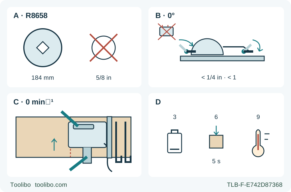
A shows a 184 mm diamond-hole blade and rejects a round 5/8 in hole. B identifies isolated zero-angle and shallow-depth settings. C shows stationary upward travel with a left blade, retained base and guide right, and both designated grips. D separates three, six and nine tool-light flashes.
A · Original diamond assembly
Match the 184 mm approved original assembly; a standard round 5/8 in blade is expressly excluded.
B · Isolated locked settings
Remove the battery, lock zero bevel and set real projection below both one full tooth and 1/4 in.
C · Supported two-grip rehearsal
Secure retained stock and guide, keep the front and rear grips accessible and route the extraction hose clear.
D · Distinct tool signals
Distinguish low battery, excessive force and heat; a delay or reset never replaces correction of the underlying fault.
A qualifies the existing original diamond-arbor assembly, not a fitting recipe. B is battery-removed control recognition: both locks must hold, with less than a full tooth and less than 1/4 in below the sample. C is an isolated stationary plan, not a running cut; upward intended travel places the blade left and broad retained support/guide right, while the body stays out of line. D shows separate tool indications: three flashes for low battery, six for excessive force with a five-second wait plus cause correction, and nine for cooling. These are not simultaneous states or charger signals.
Match the body, document and existing power system
The RIDGID R8658 rear-handle saw needs more than a familiar battery platform and a 7-1/4 in blade to establish a workable setup. Its diamond arbor, separate depth and bevel locks, two designated handles and three principal LED fault patterns are the useful starting points. This guide brings those controls together for one supported, edge-start square cut in sound wood. It is not a blade-installation or battery-charging tutorial.
Match the actual R8658 to operator’s manual 999000016, dated 6-20-22, REV:02. The current official R8658B product listing expressly identifies the included R8658 body and links to a retailer whose manufacturer-document section supplies this booklet. That establishes the document’s provenance, not a guarantee that every saw has the same supplied revision. Compare your own manual, nameplate and visible controls; stop if they differ. The commercial R8658B designation is not counted as a second mechanical model.
The manual requires batteries and chargers listed in correlation supplement 988000-302. This workflow assumes an already commissioned genuine power system that the owner can verify in that supplement and the complete instructions for the actual battery and charger. It does not name a substitute pack, derive charging steps from another RIDGID tool or treat a broad “all 18V” marketing claim as the missing correlation document. If those records or the pair’s qualification are unavailable, resolve that gap before operating the saw.
Qualify the original diamond-arbor assembly
Remove the battery before inspection. The documented blade envelope is 184 mm / 7-1/4 in and the no-load speed is 5,800 rpm. The arbor is diamond-shaped; the manual specifically rejects standard round 5/8 in arbor blades. A round-hole blade with the right diameter is therefore not an acceptable substitute, and an improvised adapter does not fix the mismatch.
Proceed only with the original approved wood blade correctly installed with its matching inner flange bushing, outer flange washer and blade screw. The diamond key must properly engage the blade and the mounting parts must be undamaged. Blade thickness and flange engagement also matter; neither a familiar tooth count nor a blade that appears centered establishes a correct assembly.
If the original installation is uncertain, has been altered or needs replacement, use the complete assembly instructions and qualified correction before continuing. The manual’s full procedure includes model-specific thread direction, contact lubrication and flange engagement. This article intentionally does not turn those details into a shortened fitting recipe or transfer a “dry flange” rule from another saw. Do not guess a tightening torque, hammer a blade into place or test an uncertain mounting under power.
Inspect the base, handles, locks and housing. The lower guard must move freely and close instantly without touching the blade or other parts at all angles and depths of cut. Check its spring and, especially after a drop, the guard and bumper. A bent, slow or nonclosing guard stops use. Do not tie or tape it open. The base-alignment service procedure elsewhere in the manual is not permission to operate with a taped guard or to begin an improvised calibration.
Prepare sound wood, support and dust collection
This workflow is for wood only. Do not fit an abrasive wheel or a nonwood blade. Choose dry, straight, known material and inspect the entire cut path for nails, screws and knots. Wet or warped lumber and concealed foreign objects are not suitable practice stock. A maintenance paragraph discussing abrasive construction dust does not broaden the stated cutting applications.
Use a stable, well-lit work area with suitable eye protection, hearing protection and dust protection. Keep bystanders clear. Secure the retained piece with clamps rather than a hand or knee. Support close to the cut and, for a large panel, near the outer edges as well. The arrangement must prevent sagging without trapping the blade as the offcut separates. Keep the saw’s base on the supported piece that remains, not on the falling waste.
For this sample, use the matched vacuum attachment and appropriate dust collector. With the pack removed, the attachment hooks over the dust-ejection port at the rear of the upper guard and is secured with its supplied screw. The manual identifies 1-1/4 in and 1-7/8 in hose connections. If the attachment is used, always connect a vacuum hose; the adapter alone is not a dust collector. Check the actual fit and route the hose so it cannot pull the saw sideways, catch a clamp or obstruct the lower guard.
Mark the retained dimension, cut line and waste side. Set a clamped straightedge for the actual base-contact edge and blade position. Do not copy another saw’s offset. A scrap trial establishes where this blade removes material relative to the 0° notch and your guide. Leave clearance for the front handle, rear handle, motor housing and hose over the whole travel.
Set depth and zero bevel with the battery removed
The depth lock sits between the guard and rear handle. Pull its lever upward to release it. Hold the base flat on the work and raise or lower the saw until the desired scale setting aligns with the depth arrow directly to the left of the lock. Push the lever downward to lock the position, then verify that it cannot shift.
Apply both depth restrictions in this booklet. The safety section requires less than a full tooth below the work; the operating text limits projection to no more than 1/4 in, while Figure 6 depicts less than 1/4 in. For this sample, set less than one full tooth and less than 1/4 in, checking the real projection under the actual stock. The quarter-inch value is an upper boundary, not a target, and maximum cutting capacity is not a thin-board setting.
The separate front bevel lock also releases upward and locks downward. Establish zero bevel and secure it. The tool has a 0–53° adjustment range, but this exercise remains square. Do not select the inner 45° guide notch for a 0° cut. The documented positive stops and the existence of a high-angle range do not replace a locked setting and a verified sample.
If the locks fail to hold, a lever contacts another part before securing the setting, or the sample is not square despite a sound layout, stop. Lever reindexing, base alignment and zero-stop correction belong to complete matched instructions and competent service, not adjustments made around a running saw. This guide does not combine the conflicting product-table and manual figures for 45° cutting capacity.
Rehearse the two-handle travel before connecting power
The rear handle carries the trigger; the other hand belongs on the front handle. Keep both hands on their designated grips during the cut, with neither hand on the workpiece or below it. Stand out of the blade’s line, arranging the cut to your right as shown in the manual. The position of the broader base is not an instruction to place your body on that same side.
With the battery still removed, check the entire approach, guide contact and exit clearance. In the conceptual plan view, intended travel is upward, the blade/cut is on the left of the saw and the broader retained support and guide are on the right. This matches the actual operating perspective, not the mirrored underside view used for service alignment. The diagram is a stationary rehearsal, not an instruction to hold a moving blade exposed.
Recognize the actual trigger: depressing it starts the saw and releasing it stops the drive. Do not invent a separate lock-off button from generic wording elsewhere in the booklet. Trigger release and an extinguished worklight are not physical isolation. Remove the pack for adjustments, cleaning, accessory work and nonuse.
Follow the actual power-system instructions before fitting a qualified pack. The tool manual prohibits use, storage or charging below 50°F or above 100°F, wet charging and outdoor or vehicle storage. Reject damaged or modified packs. With the trigger released and hands clear, insert the correct pack and verify that both side latches engage securely. Do not force a poor fit or bypass a latch.
Cut, stop and interpret interruptions
Rest the front of the base on the supported work with the blade clear of the entry edge. Take both grips, start the saw and wait for full speed before entering the wood. Keep the base flat and feed smoothly forward along the guide. Do not force the motor, twist the blade to recover a wandering line or reach for the offcut.
If the blade binds or the cut must be interrupted, release the trigger and hold the saw motionless until the blade completely stops. Never pull it backward or lift it from the work while it is moving. Remove the pack before correcting support, guide alignment, depth or blade-condition problems. A restart in an existing kerf requires the blade centered and teeth clear of the material; an unresolved pinch is not a restart condition.
Read the worklight patterns as separate tool states, not charger indications:
- Three flashes mean low battery. Stop and use the already qualified power-system procedure rather than pushing through the cut.
- Six flashes indicate excessive force; the table specifies waiting five seconds. Also correct the cause of loading or binding before another attempt. Waiting alone does not repair the setup.
- Nine flashes indicate overtemperature. Let the tool cool and investigate the load and operating conditions.
- More than nine flashes call for removing the battery and reinserting it a few minutes later. This is not permission to repeatedly reset a damaged or unexplained fault. If it persists, stop and obtain service.
At normal completion, keep control, release the trigger and wait for complete standstill before removing or setting down the saw. Confirm the lower guard covers the blade. Product marketing mentions an electronic brake, but this workflow supplies no invented stopping-time guarantee; neither a brake nor a dark LED substitutes for observing standstill and guard closure.
Accept the sample and leave a stable setup
Remove the pack before measuring the retained dimension and checking squareness. Look for guide or clamp movement, torn edges, burn marks, unusual vibration and evidence that the offcut closed the kerf. An apparently straight edge is not acceptance if the support shifted or a guard malfunctioned. Correct the isolated setup and repeat a sample when necessary; persistent faults require qualified service rather than repeated loaded tests.
Clean accessible dirt and dust with a clean cloth while the pack is removed. Avoid solvents on plastics and do not expose them to petroleum products or penetrating oils. This guide does not prescribe a chemical blade-cleaning treatment or open internal parts. Store the tool and qualified power system dry, within their stated conditions and out of children’s reach. Record the successful material, depth and guide setting, keeping the matched manual and power-system documents with the tool.
Models referenced