
Separate the qualification evidence from the operating controls
A shows a detached battery and a 7-1/4 in blade with 5/8 in bore rated above 5000 rpm. B separates upward release and downward locking arrows for depth lever 19 beside a partial-tooth projection. C identifies zero-bevel knob 16 and original handle numbers 3 and 7 without a running pose. D pairs tool-side and extractor instruction sheets as separate prerequisites.
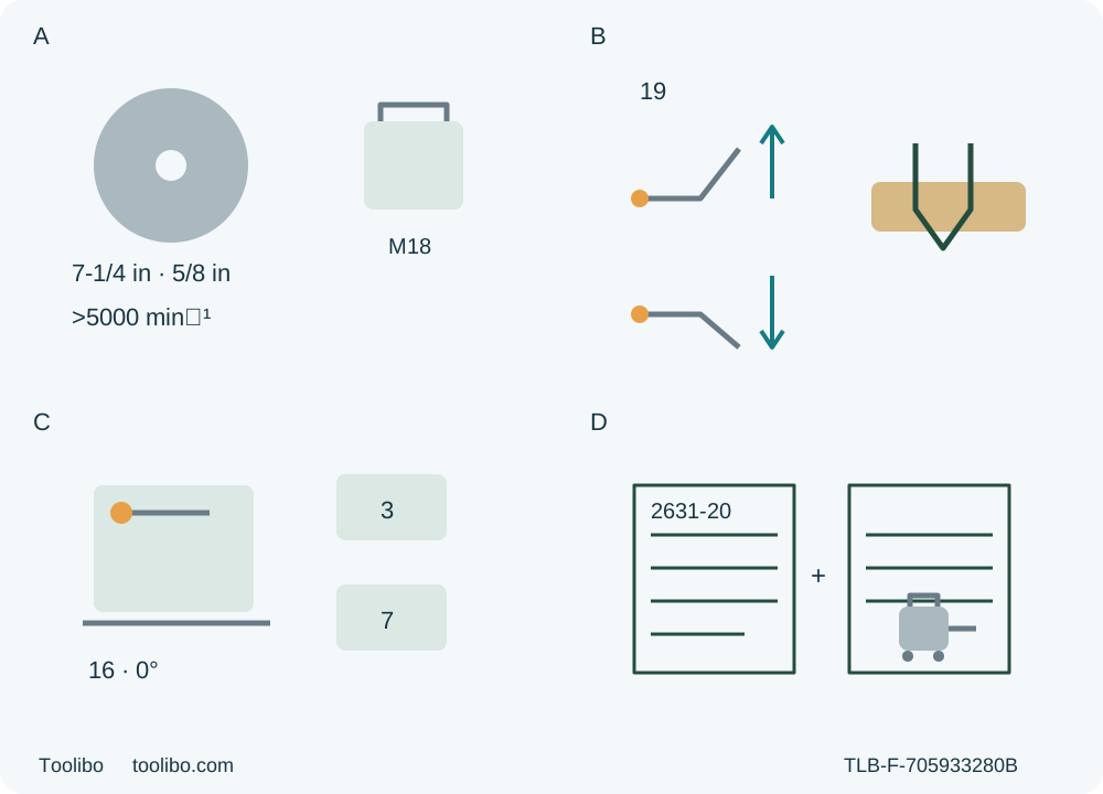
A · Verify existing assembly and power
Actual original thin-kerf 7-1/4 in/5/8 in wood blade must be rated above 5000 rpm and already correctly assembled. Remove the actual commissioned M18 pack before all checks.
B · Use the correct depth lever
With the pack out, lift lever 19 toward the motor to release, set actual through-cut depth with less than a full tooth below stock, then press the lever down securely.
C · Keep controls distinct
Single bevel knob 16 locks zero; main grip 7 and front grip 3 remain the operating handles. The isolated guard test uses the owner manual side position, not a service-bulletin substitute.
D · Require both dust instruction sets
Native tool-side connection/hardware and actual extractor instructions must already establish a qualified operating arrangement. Missing evidence holds the whole cut; optional parts alone do not close it.
Conceptual isolated symbols are not to scale. A does not authorize fitting or a new battery pairing. B preserves the less-than-full-tooth rule rather than a universal 6 mm projection; the up/down arrows concern only the depth lever. C identifies controls, not grip/body geometry or a guard test. D requires the actual native manufacturer and extractor instructions with already commissioned hardware/performance; it supplies no adapter, hose or pressure value. The owner guard procedure remains side-position only plus all-angle/depth clearance, not the service bulletin pose.
This is an existing-owner workflow for the US Milwaukee 2631-20 M18 Brushless 7-1/4 in circular saw, matched to operator manual 58146400d1, March 2018. It takes a sound, already qualified original system through one ordinary square crosscut in known loose wood and an isolated acceptance check. It does not commission a new blade, battery/charger pair or dust adapter.
Three conditions must be established before any cut: the original blade and mounting hardware are already correctly qualified; the actual designated M18 power system is already commissioned under its complete instructions; and the native extraction arrangement is already documented and qualified on both the tool and extractor sides. If any is unavailable, stop at a specific evidence or service handoff rather than continue with a generic “suitable” accessory.
Match this body and preserve its service boundary
Confirm 2631-20 on the actual nameplate, the visible controls and the supplied complete instructions. The selected current US product page links the d1 manual. This is not the smaller 2630-20, even though a different document filename for that other saw contains the digits 2631. Nor is it the 2834 body or a separately counted battery kit.
The operator manual specifies 18 V DC, 5000 no-load rpm, a 7-1/4 in blade and 5/8 in arbor. Use the already correctly installed original, approved thin-kerf wood blade, with its actual instructions, undamaged teeth and a maximum safe operating speed greater than 5000 rpm. A picture of a blade on a product page is not a guaranteed supplied SKU or approval of the blade currently on your saw. Unknown blade identity, rating, hole shape, suitability or mounting history is a hold.
There is an unresolved documentary problem with blade fitting: the operator text gives turn directions while the actual linked August 2023 parts bulletin names a left-hand blade screw. This guide does not choose a direction, try the bolt, give torque or assemble a replacement. If fitting is needed or the existing hardware is uncertain, provide the exact model, serial and documents to Milwaukee or qualified service for clarification. The parts bulletin is supporting conflict context only; its repair, wiring and lubrication content is not an owner procedure.
Establish the saw’s material history. If it has been used on metal or masonry, the manual requires reserving and marking it for that purpose and returning it to a Milwaukee service facility for cleaning and testing before wood use. Unknown history or an unqualified return to wood is a hold, even if a visible guard seems to move normally. This workflow excludes metal, masonry, abrasive/diamond work and the manual’s conflicting nonwood branches.
Confirm actual power and extraction before preparing stock
Use only the specifically designated, sound M18 pack and its specified M18 charger whose complete matching instructions have already been followed. Record the actual identities; family names alone do not commission a pair. Product discussion of an XC5.0 does not prove it is included or approve a new combination. Charging, first-time power setup and electrical repair are outside this guide. A damaged or modified pack or tool must not be used, and damaged batteries are not owner-service items. Protect terminals from metal objects, moisture, heat and impact. The manual recommends ambient operation from 0°F to 125°F; this is not a charging temperature table.
The current product describes an integrated dust port, and the parts document lists optional adapters. Those facts do not supply a complete tool-side installation procedure. For this task you must already possess the correct manufacturer’s instructions for the actual native connection/hardware and the extractor’s own instructions, with the complete arrangement previously commissioned and its required performance established. If that tool-side evidence is missing, hold before cutting and obtain manufacturer/equipment qualification. Do not infer a 49-90-3001 or 3002 fit, hose diameter or installation sequence from an exploded drawing or from another Milwaukee model.
Before making or checking hose connections, switch the tool OFF, wait for complete blade standstill and remove the battery; isolate the extractor under its own instructions. Connect and operate only that already qualified system under its own instructions. Confirm effective extraction before the cut and route the hose so it cannot snag, pull the saw or obstruct the guard. A bare port or an attached but inactive hose is not dust control. No invented pressure/flow figure or capture percentage is supplied here. Use good ventilation and approved respiratory protection appropriate for microscopic particles, alongside safety goggles or glasses with side shields and hearing protection appropriate to the conditions. Do not use dust equipment as a reason to omit the required personal protection.
Remove the pack and inspect the sound tool
Release the trigger and wait for complete blade standstill. Press the battery release buttons and pull the pack completely away from the tool. Keep it removed during all guard checks, depth/bevel preparation, inspection and cleaning. A released trigger is not isolation.
Inspect the body, shoe, handles, switch, locks and accessible original mounting hardware. Reject cracked or broken teeth, a dull or bent blade, loose or incorrect washers/bolt, damaged guards, misalignment, binding, undue noise history or any unexplained defect. The switch must be sound and controllable; a suspected switch or brake fault goes to service rather than an energized demonstration. Remove the adjusting wrench before reconnecting power. Keep handles clean, dry and free of oil or grease.
Before each use, check free and immediate lower-guard closure, spring operation and clearance from the blade and all other parts at all angles and depths of cut, especially after a drop. The owner manual also specifies a particular isolated check: place the tool on its side, grasp the lower guard by its sides without contacting the teeth, push it fully back into the blade housing and release it. It must spring back immediately. The manual warns that this check does not show proper operation if the tool is not on its side.
If accessible chips prevent return, keep the pack out and clean the upper/lower guard area as the manual permits, then repeat the same isolated check. Persistent failure requires a Milwaukee service facility; do not repair the spring or defeat the guard. The parts bulletin’s upside-down service check is a different context and is not combined with this owner procedure. If the actual guard cannot be checked safely under the complete instructions, hold. For this ordinary edge-entry cut, the lower guard works automatically and is never tied or held open.
Plan the complete crosscut and both pieces
Choose clean, dry, untreated loose wood and an original blade approved for crosscutting that wood. Inspect the full cut route and remaining stock for nails, stones or other foreign material. Exclude unknown coatings, hidden services and installed materials. Keep the workplace dry, well lit and clear of flammable liquids, gases, dust accumulations and bystanders. Do not work tired or beyond your ability; obtain trained help when the actual task cannot be controlled.
Mark a square line from a verified reference edge, identify the retained part and waste, and allow for the actual kerf on the waste side. A familiar sight line does not determine a finished dimension until the sample is measured. This is a complete edge-to-edge crosscut, not a stopped interior cut, narrow-strip ripping setup or plunge.
Clamp the retained work to a stable bench or sawhorse arrangement. Support both portions near the cut and edges as the actual stock requires, leaving the blade path and the space below it clear. Waste must remain independently supported and free to separate without closing the kerf. Do not hold the work in a hand or across a leg, and do not bridge a clamp across the cut in a way that traps the blade. The manual warns that sagging long stock or panels can bind the blade; a small-looking sample still needs real support.
With the saw isolated and blade guarded, inspect the intended entry, travel and clear exit beside or safely above the line. Do not push projected teeth through uncut material as a rehearsal. Confirm that the shoe can remain flat, both original grips remain available, the hose clears clamps and guard, and the operator can finish without overreaching. If this cannot be established, use a different qualified workholding arrangement or hold the cut. No universal minimum offcut length or unsupported overhang is certified here.
Set the actual depth and zero bevel
With the battery removed, hold the saw by its handle and push depth lever 19 up toward the motor housing to release it. Raise or lower the shoe to the required position, then press the lever down to secure it. Do not import another model’s opposite lever sequence.
The safety section requires less than a full tooth below the work. The depth paragraph also describes no more than 1/8–1/4 in and illustrates 1/4 in/6 mm. Retain the stricter actual partial-tooth requirement: the blade must cut through the measured stock while less than one complete tooth projects beneath, and it must not cut into supports. The numeric passage does not make 6 mm a universal depth setting or mean that a full tooth may be exposed. If the actual installed blade cannot satisfy through-cutting, clearance and partial-tooth conditions, hold rather than guess.
For the square sample, hold the handle, loosen bevel knob 16, support the front of the shoe and rotate the saw to zero using the actual bevel scale and indicator edge. Tighten the knob securely. The original blade-to-shoe square relationship must already be correct; check it under the complete isolated instructions. If it is not, obtain qualified correction rather than improvise adjustment-screw calibration here. Confirm that both depth and bevel are locked. The maximum 2-1/2 in square and 1-7/8 in at 45° specifications are not the sample’s required depth or permission for a bevel project.
Reconnect and make one sound-tool sample
Finish the isolated checks, remove the wrench and ensure the switch is off. Slide the qualified charged pack into the body until it latches securely. Verify the qualified extraction is operating and its hose remains free. Do not reconnect a tool that failed an earlier condition.
Put one hand on main handle 7 and the other on front handle 3, using the intended gripping surfaces. Keep the body to either side of the blade line rather than in line with it, with stable footing and arms ready to resist a reaction. Hands remain away from the cutting area, moving parts and underside of the work; neither hand supports the stock or catches waste.
Place the front of shoe 10 on the supported workpiece edge with the blade clear. Align the appropriate actual sight line 1 to the marked square cut. Push lock-off 5 down while pulling trigger 6, and allow the motor to reach full speed before blade contact. Keep the shoe flat and advance smoothly across the grain without forcing or twisting. The original lower guard opens and returns automatically. If the line is being lost, do not steer forcibly back through the kerf.
On binding, stalling or interruption, release the trigger immediately and hold the saw motionless in the material until complete stop. Never withdraw or pull a moving blade backwards. Investigate only after safe isolation, and obtain qualified help for a trapped or unexplained condition. This guide does not teach restarting within an old kerf or reproducing a fault under power.
Complete the stop and acceptance decision
After full separation, release the trigger. Maintain control until actual blade standstill, confirm the lower guard has closed, and only then remove the saw from the work and set it down safely. Remove the battery before measurement or inspection. Do not reach for the offcut while the blade is coasting.
The electric brake generally stops the blade within two seconds, but the manual explicitly allows delay or an occasional missed engagement. This is not a countdown or a substitute for the guard. Frequent misses require an authorized Milwaukee service facility. Do not perform repeated powered fault tests or rely on elapsed time instead of actual standstill.
With the pack out, check the finished length against the intended line and kerf allowance, square across the width and through the thickness, and both faces for splitting, burning or unusual tooth marks. Confirm no workholding movement, loose setting, abnormal heat or extraction loss occurred. The finished sample passes only when dimensional, surface and process checks all meet the task’s requirements. The manual’s troubleshooting list gives possible causes, not a diagnosis authorizing a blade change or electrical repair. A wrong dimension does not authorize a loose tiny recut; re-plan on adequately supported material or hold.
Keep the tool, battery and charger maintained under their full instructions. Before maintenance, unplug the charger and remove the battery from the tool and charger. Isolated accessible cleaning uses clean vents and dry grips; the manual permits mild soap and a damp cloth, not solvent baths, flammable cleaners or liquid entering the equipment. Do not disassemble the tool, pack or charger. Follow the stated inspection/service schedule, including the six-month-to-one-year interval depending on use. Record exact model, serial, original blade/history, power and extraction evidence, settings and sample result. If any prerequisite remains unresolved, the useful finished outcome is a specific hold and service/document request—not an implied permission to cut.
Models referenced