
Identify the isolated controls before qualifying the whole path
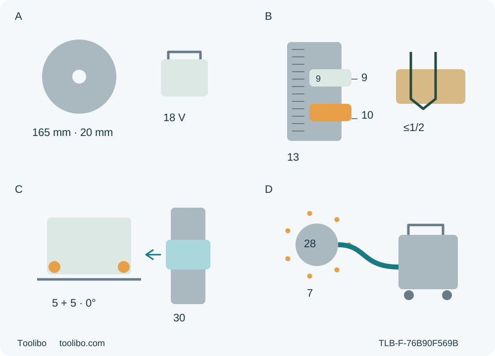
A shows the original 165 mm blade with 20 mm bore and detached battery. B separates ordinary depth reference 10 from FS 9 beside a half-tooth concept. C shows both zero-bevel locks 5 and the central glass-guard position 30. D shows seven indexed connector positions 28 and a connected extractor.
A · Match the existing system
Actual 01866001/0526, original qualified 628026000 and commissioned 625368000/ASC 145 must be established before setup; remove the battery.
B · Read the ordinary depth edge
Battery out: press, move and release button 13; use edge 10 rather than FS 9 and verify actual through-cut with at most half-tooth projection.
C · Set the square-cut controls
Battery out: lock both bevel screws 5 at zero and put glass guard 30 centrally. Cordless wood speed is wheel 21 at 12, not the corded column’s 6.
D · Qualify active extraction
With tool and extractor isolated, push connector 28 in, rotate and pull out to lock; seven positions. Verify the actual suitable extractor and clear hose route before cutting.
Conceptual isolated symbols are not to scale and supply no fitting or support-fixture design. B means actual through-cut with no more than half a tooth exposed, not a factory depth offset. C central glass applies only to this zero-degree no-rail scope. D counts seven lock positions, not pressure or flow. The full-base start, clear normal exit and immediate interruption stop remain separate requirements in the text.
This workflow is for an existing UK Metabo KT 18 LTX 66 BL whose actual technical identity is 01866001 and whose supplied instructions match 17027886_00_0526. Its outcome is one controlled, open-ended straight sample in known loose wood, followed by an isolated dimensional and condition check. It is not a first-time plunge-saw commissioning guide, an enclosed opening or an invitation to copy a front-shoe-only start from another circular saw.
The decisive planning question is whether this actual setup can support the complete guide plate from the guarded start through a fully clear normal exit. If it cannot, hold the task. A more powerful battery, a shallow setting or a clean pencil line does not replace that support and clearance evidence.
1. Match the existing tool and original assembly
Read the actual rating plate, supplied manual and exact service identity together. The UK product route and 01866001 service page support this scope; they do not establish that every 01866000 or similarly named machine has identical applicability. The manual also covers the corded KT 66 BL. Its mains supply provisions and six-position wood-speed recommendation are not instructions for this cordless body.
Retain only the already correctly fitted, genuine 628026000 wood blade, identified as 165 × 20 mm, 42 WZ, with original approved mounting hardware and the correct 20 mm flange orientation. Confirm actual blade approval, sharpness, cleanliness, absence of damage and a permitted speed suitable for the tool’s maximum 5000 rpm. The manual specifies a 1.0–2.0 mm blade body and a maximum 2.6 mm cutting width; wood blades must conform to EN 847-1. A matching diameter alone is not qualification. Unknown blade identity, rating, bore, flange orientation or previous fitting work means hold for exact qualified correction.
This guide does not flip the reversible flange, adapt a 5/8 in blade, turn blade-changing lever 14, select a bolt torque or replace a blade. Accessible loose or incorrect hardware, a cracked or distorted blade, sticky deposits, abnormal rubbing or an unexplained mechanical condition must be resolved before use, not investigated by powering the saw. Keep the supplied general safety instructions with the tool manual.
2. Qualify the actual power and dust systems
Use the actual genuine 18 V LiHD 625368000 5.5 Ah pack and ASC 145 charger only as an already commissioned combination with their complete matching instructions. Both appear in this manual’s accessory page, but that page is not a charging tutorial or proof of a carton bundle. The pack must already have been correctly charged and be sound; do not start with an unknown charger history. No generic CAS interchangeability or larger-pack photograph establishes a different pairing here.
Keep packs away from water, fire and metal objects that could bridge terminals. Do not use damaged, deformed or modified batteries, open a pack or attempt battery repair. The tool’s permitted operating ambient range is −20°C to 50°C, with reduced performance below 0°C; storage is 0°C to 30°C. These are not charger temperature instructions. If the existing system or actual conditions are outside its complete instructions, stop before the sample.
Use a suitable active extraction unit with the actual qualified suction hose and connector 28, under the extractor’s complete instructions. Confirm suitability for the material, filtration, collection and actual operating arrangement; a fitted hose that is not extracting is not enough. This manual supplies no Bosch-style installed pressure/flow threshold, and none is imported. A dust bag is not a substitute in this selected workflow.
Before making or checking connections, release the trigger, wait for full blade standstill, remove the battery and isolate the extractor under its instructions. Connector 28 is positioned by pushing it fully in, rotating to the desired direction and pulling it out again to lock. It has seven indexed positions, not eight. Confirm it cannot rotate unintentionally and that the hose will not snag, pull the saw or obstruct the moving head. Operate and check the qualified extractor before cutting.
Wear protective goggles, ear protection and a suitable dust-protection mask. Provide good ventilation, keep others away from the dust stream and collect particles at their source. Use a vacuum for workplace dust; blowing or dry sweeping redistributes it. Clean, dry clothing and non-slip footing, secured hair and no loose jewellery are part of the preparation, not substitutes for extraction.
3. Inspect the guarded head with the battery out
Switch OFF, wait for complete standstill, press release 19 and remove battery 24 completely. Keep it out for inspection, settings and cleaning. Check the switch and locking controls, both grips, guide plate, glass guard and accessible hardware. A switch that cannot reliably control the tool, damaged parts or binding requires qualified service. Remove adjustment keys before reconnecting power.
Before each use, the guard must move freely and enclose the blade immediately; check its clearance from the blade and other parts at all angles and depths of cut, including after a drop. Check the return spring and the movable motor section: it must return automatically, smoothly and precisely to its upper end position. Sluggishness, damage or debris that prevents correct operation is a service hold. Never tie the guard open or clamp the motor section down.
Pushing locking button 17 forward permits the head to lower and the blade to emerge even when the battery is removed. Keep fingers away from the blade and underside throughout controlled isolated checks. Do not improvise a pendulum-guard lever check from a different saw. Blade-changing lever 14 is not an operating lock for this task; the head must already be in its normal freely returning condition.
4. Set the no-rail square-cut controls
With the battery still out, loosen both bevel locking screws 5, set the motor section to zero on scale 4 and retighten both. Do not use undercut button 6 or adjust the factory angle screws. If the actual square relationship is doubtful, obtain correction rather than compensate with a tilted guide.
Press depth locking button 13, move the setting, read the ordinary depth edge 10 and release the button to secure it. The separate edge marked FS, number 9, is for the guide rail and is not the reading for this rail-free sample. Do not add an invented rail-thickness correction. Establish actual through-cut depth with no more than half of each tooth projecting below the workpiece, preserving the general less-than-full-tooth rule. The scale alone does not prove actual projection; inspect the isolated geometry without touching teeth. If complete separation and the projection limit cannot both be established, hold.
Set glass guard 30 to its central position for the zero-degree cut. Its upper bevel position and lower rail position are different; neither is borrowed here. Missing, damaged or incorrectly positioned glass is not waived for visibility. Use wheel 21 at 12, the cordless column’s wood recommendation. The adjacent corded column says 6; that is not an equivalent setting on this tool. This is a documented selection, not a promise about feed rate or finish. Leave the fine-depth calibration wheel and rail-fit adjustments outside the procedure.
5. Design the complete base-on-stock path
Keep the workplace and tool dry; do not work in explosive atmospheres or in the presence of flammable liquids, gases or dust. Choose sound, clean, dry loose wood that the retained original blade is approved to cut. Inspect the complete route and remaining stock for nails, stones and other foreign material. Exclude installed panels, hidden services, unknown coatings, metal, plastic and extremely small workpieces. Mark the desired straight path and identify retained material and waste before arranging supports.
Secure the retained work against movement on a stable platform. Support both portions independently, near the cut and outer edges as needed to prevent sagging, without placing any support in the blade path. The waste must separate without pinching the kerf; do not clamp the two portions across the cut or hold waste by hand. No universal overhang, minimum remnant length or support-load figure is asserted.
Use a sound straightedge securely attached to the workpiece, with the guide plate running against it as described by the manual. Establish its actual offset for this original blade, contact side and square setting; do not assume a factory dimension. The left, red-marked edge of indicator 2 identifies the vertical-blade line. That indicator does not certify the actual guide offset or final edge.
The start must allow the complete guide plate to rest flat on supported stock with the motor section uppermost and the blade contained above the plate. The route must continue to an open end where the entire cutting arc can clear the material while the base remains stably supported and both hands retain control. Merely seeing the front of the blade cross the pencil line does not establish a clear exit. Do not arrange an enclosed opening or plan to lift a moving blade out of an uncleared kerf.
With power isolated and the blade covered, check reach, hose travel, straightedge and clamp clearance beside or safely above the route without tooth contact. Both grips must remain available from start to finish; do not reach under stock or across the cutting area. If actual geometry cannot provide full support, a clear arc and a controlled stopped removal, obtain qualified task planning or hold. This guide supplies no unverified bridging fixture, foam underlay or improvised backer design.
6. Make the sound-tool sample and distinguish the two stop routes
After the isolated checks, remove keys and loose objects, confirm the trigger is OFF and slide the already qualified pack in until it engages securely. Activate and verify the prepared extractor. Use handle 11 and additional handle 12, keeping the insulated gripping surfaces firmly controlled, hands clear of the cutting area and underside, and your body to either side rather than in the blade line. Maintain stable footing without overreaching.
Place guide plate 16 fully on the qualified supported stock with the motor section uppermost and blade not projecting. Push locking button 17 forward and hold it, then actuate trigger 18. Let the blade reach full speed before contact. Lower the motor section slowly to the preset depth, then move slowly forward along the guide. Maintain flat support and two-hand control; do not twist, force feed or steer sideways against the blade. The head must not be clamped down.
For a normal uninterrupted completion, continue only through the prequalified clear exit until the whole blade arc is out of contact with the stock, while maintaining stable base support. Release trigger 18, hold the saw controlled and wait for actual complete standstill before removing it from the material. Allow the motor section to return freely and completely upward under control; confirm the guard covers the blade before setting down. Remove the battery before measurement or inspection. Do not switch normally on or off with the blade touching the workpiece, and do not lift or withdraw a rotating blade.
For binding or interruption, the safety rule overrides that normal exit sequence: release the trigger immediately and hold the saw motionless until the blade stops. Do not keep feeding merely to reach the clear exit, pull backwards, lift it while turning or use another trigger pull as a test. Isolate when safely possible and obtain qualified resolution of the cause; this guide does not teach a trapped-tool extraction or restart.
The monitoring system is not isolation. Automatic protection may sound a continuous warning until trigger release or a maximum of 30 seconds. A kickback shutdown has three beeps and three flashes of indicator 20. These are stop/assessment events, not permission to resume; this workflow does not perform reset tests, idling-cooling runs or charger cooling procedures.
7. Accept the sample, or record a specific hold
With the battery out and all movement stopped, inspect both faces, the entire cut edge and the remaining work. Confirm complete separation, the planned line/width at entry, middle and exit, straightness and square edge geometry using appropriate measuring tools. Look for burning, tearing, unusual rubbing, damaged teeth, shifted clamps or supports, and inadequate dust capture. No universal dimensional tolerance or tear-free guarantee is promised. A poor result is evidence to investigate, not permission to force another pass or trim a small loose offcut.
Record the exact 01866001/0526 identity, original blade and power evidence, depth edge and actual projection, both bevel locks, glass position, wood speed, extraction arrangement and sample observations. Keep product and manual weight/noise figures separate where their bases differ; neither determines the success of this sample.
After use, keep the battery removed. Regularly remove dust with appropriate extraction, including vacuum cleaning the motor ventilation slots, and keep safety mechanisms freely returning. Do not blow hazardous dust, introduce cleaning chemicals, disassemble the head or undertake electrical repairs. Store securely under the complete instructions. An unresolved identity, guard, assembly, support, exit or dust requirement ends in a documented hold—not a partly qualified cut.
Models referenced