
Four isolated checks for the KS 85 FS
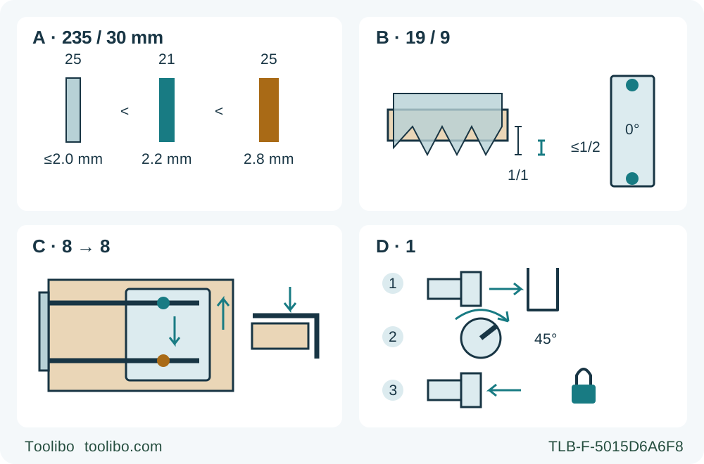
A compares a maximum 2.0 mm blade plate, 2.2 mm knife and 2.8 mm kerf for the documented original 235/30 mm assembly. B shows no more than half-tooth projection and two zero-bevel locks. C shows transverse fence bars and front-then-rear locks with the fence rail down. D shows nozzle push, indexed rotation and pull to lock.
A · Matched blade and knife
Keep the original regional assembly; the plate is thinner than the 2.2 mm knife and the 2.8 mm kerf wider. Verify both separate knife gaps, each at most 5 mm.
B · Half-tooth and two locks
Unplug, secure depth lock 19 with no more than half a tooth below the work, then secure both bevel screws 9 at zero.
C · Fence rail alignment
Set the edge-following rail parallel to the blade and downward for the workpiece edge; tighten front guide lock 8 before rear lock 8.
D · Indexed dust outlet
Push nozzle 1 fully inward, rotate and pull out to engage a 45° indexed position; route suitable extraction clear of the work and protective parts.
All panels are unplugged control or qualification checks, not a running cut or replacement procedure. A applies only to the documented original regional 235 × 30 mm assembly; the multi-region manual also lists 15.88 mm, not an interchangeable-fit promise. Both knife clearances—inner curve to teeth and blade lowest point below knife bottom—must be at most 5 mm, though not drawn here. B identifies depth lock 19 and both bevel locks 9. C means the edge-following fence rail is parallel to the blade, not the transverse bars; lock front 8 then rear 8, with the rail down for a workpiece edge. D is nozzle 1: push fully in, rotate in 45° steps and pull out to lock, then connect suitable extraction.
Use the knife, blade and controls as one system
The Metabo KS 85 FS combines a 235 mm blade, a movable riving knife, a two-bar parallel guide and a depth setting illustrated in half-tooth increments. Those features need to agree before a cut; the large blade diameter does not make this an unrestricted deep-cut or plunge saw. This workflow prepares an existing correctly assembled machine for a supported, edge-start square cut in known wood, then checks the result and the condition of the protective parts.
Match the actual tool to service identity 01085000, product 601085000 and operating manual 17027686_00_0526, together with the linked general safety instructions 17030000_00_1025. The current official product identifies the 220–240 V, 50–60 Hz version, while the actual nameplate must govern the supply used. A different regional tool or mismatched documentation needs its own verification, not an assumption based on the shared KS 85 FS name.
The manual explicitly says the machine is not designed for plunge cuts. Generic guard wording elsewhere that mentions special cuts does not override that model-specific restriction. Although the stated applications include plastics and similar materials, this article uses known, untreated wood with the already installed approved wood blade. It does not cover plastic, abrasive cutting, hidden services, guide-rail installation or mitre-rail work.
Keep the original bore and flange arrangement qualified
Unplug before inspection. The documented no-load speed is 4,500 rpm, and the original blade must be suitable for that speed, the material and the machine’s marked diameter. Use the correctly fitted genuine Metabo blade and matching mounting parts; the wood blade must conform to EN 847-1. Cracked, bent, dull or unsuitable blades, HSS blades and uncertain installations are stop conditions, not reasons to try a slower feed first.
The exact current European product lists 235 × 30 mm. The multi-region manual also lists 15.88 mm / 5/8 in and describes two sides of the inner flange. That is not permission to substitute either bore on any machine or reverse a flange by guesswork. This owner workflow retains the original correctly matched 30 mm assembly for the documented version. If the mounting or regional identity is uncertain, stop for the complete matched assembly instructions and qualified correction.
The manual includes a blade-change procedure with model-specific screw direction and flange orientation. This article deliberately does not shorten it into a replacement recipe, propose a torque, or suggest a conversion. A blade that fits the spindle is still unacceptable if its plate and cutting width are wrong for the riving knife.
Check the riving knife’s relationship and movement
The specification table gives a maximum blade-body thickness of 2.0 mm, a cutting width of 2.8 mm and a riving-knife thickness of 2.2 mm. The important relationship is that the blade body is thinner than the knife and the teeth cut wider than the knife. The knife must fit in the kerf while resisting the wood closing behind the blade. Do not confuse the thin central plate with the wider tooth path.
Two separate clearance checks are shown on page 3. The gap from the knife’s inner curve to the blade’s toothed rim must be no greater than 5 mm. Separately, the blade’s lowest point must not extend more than 5 mm below the knife’s bottom edge. These are not two readings of one radial gap. Both belong to the qualification of the installed assembly.
The knife must be correctly fitted, aligned and undamaged. Both it and the lower guard must move freely and return automatically and accurately to their end positions. Check with the tool unplugged, keeping fingers clear of teeth and using the designated guard control where appropriate. The guard must close instantly and must not touch the blade or other parts at all angles and depths of cut. A bent knife, sluggish return, damaged spring or interfering guard stops use.
This is an inspection boundary, not an instruction to loosen the two knife-setting screws and adjust by eye. If either clearance or alignment is uncertain, obtain competent correction under the complete instructions before cutting. Never remove, bend or tie back the knife or guard to make a cut possible. The knife only performs its intended role while engaged in the work; the manual warns that it is ineffective in preventing kickback during short cuts. It does not replace support, sharp teeth, secure settings or two-hand control.
Establish supply, extraction and support
Check that the supply voltage and frequency match the actual nameplate. The tool manual requires an upstream RCD with a maximum trip current of 30 mA. An RCD does not excuse a damaged cable, an unsuitable extension or a wet work area. Keep the plug disconnected while setting the tool and route the cable so the full cut can be completed without a snag or contact with the blade.
Use suitable extraction and connect its hose to nozzle 1. To position that nozzle, push it fully inward, rotate it to the desired direction, then pull it out again to engage the indexed position. It locks in 45° steps. Do not leave it partly seated or assume that merely pointing the outlet away amounts to dust collection. Check the actual hose fit and keep the hose clear of the guard, riving knife, grips, guide and travel route. No universal hose diameter is asserted here.
Use suitable eye, hearing and dust protection and adequate ventilation. Do not process material producing prohibited hazardous dust, such as asbestos. Inspect wood for nails and other foreign objects. Known clean stock is the appropriate sample; unknown coatings and chemical treatment introduce hazards that a familiar blade cannot resolve.
Clamp the work to a stable platform, keeping the larger retained area available to support the base. Keep the blade’s underside path clear of clamps, supports and fasteners. Support panels on both sides near the cut and near their outer edges, without trapping the offcut or closing the kerf. Do not attempt extremely small pieces or use a hand beneath the stock to steady it.
Set half-tooth depth and lock both bevel points
With the plug disconnected, release depth locking screw 19. Raise or lower the motor section relative to guide plate 16, read depth scale 20 and retighten the lock. The model’s setting guidance recommends no more than half of each tooth projecting below the work. Use that stricter working setting for the sample rather than treating the general less-than-one-tooth warning or the maximum 85 mm capacity as the target.
Check the real projection under the actual board and verify that the depth cannot shift. A lock that bottoms out or fails to hold needs correction before use. The manual describes lever reindexing, but that service adjustment is not part of this cutting workflow.
Two separate locking screws 9 secure the bevel setting. Release both only while unplugged, establish zero on scale 7 and retighten both. Stop 6 permits increasing the maximum bevel range from 45° to 48° when pushed down; it is not the angle lock and does not need to be operated for this square cut. Do not mistake either bevel screw for one of the parallel-guide locks 8.
If a zero setting does not produce a square sample, inspect the setup and seek complete correction instructions rather than turning angle-adjustment screw 15 during a cutting attempt. A familiar scale position is not proof of a secured or calibrated assembly.
Align the fence rail, then lock front and rear
The double parallel stop 12 can enter its supports from either side. For following a straight workpiece edge, install it with its edge-following stop rail facing downward. The manual’s upward-facing arrangement follows a straight edge on top of the workpiece; these are different reference arrangements, not interchangeable fence positions.
Set the edge-following fence rail parallel to the saw blade. The two transverse bars carry the fence; they are not supposed to run parallel to the blade. With the intended width set, tighten the front guide locking screw 8 first and the rear one second. Check that tightening has not skewed the fence and that it follows a sound, straight reference edge without forcing the saw sideways.
Use a scrap trial to establish the actual cut width. Cutting indicator 11 has a left 0° notch for a vertical blade and a right 45° notch for that bevel; use the left zero notch here. The reference does not eliminate kerf width or prove the scale matches the finished edge. Mark the retained dimension and waste side, then verify where the original blade actually removes material.
A separately clamped straightedge is another documented way to guide the base, but it still needs its own measured offset and clearance check. This article does not turn the brand names printed beside the base’s guide grooves into a universal rail installation procedure. Keep this first sample on the verified edge-guide arrangement.
Rehearse, start and finish without defeating protection
While unplugged, inspect the full route with both designated grips available: handle 2 and side handle 5. Keep the body to one side of the blade’s line, not behind it, and keep both hands away from the underside of the work. Check that the fence, hose and cord cannot catch, that the base stays supported and that no clamp obstructs a handle or housing.
Recognize the starting sequence before connection: push locking button 4 forward and hold it, then actuate trigger 3. Releasing the trigger stops the drive. The lock button is not electrical isolation; unplug for any adjustment, inspection, accessory work or cleaning. Do not bypass an unreliable switch or guard.
Once all settings and the work are secure and the trigger is released, connect to the matched protected supply. Place the front of the base on the work with the blade clear of the entry edge. Take both grips, start and wait for full speed, then advance smoothly forward along the reference. Do not force the feed or twist the blade to recover a wandering line.
For a normal completion, maintain support and let the blade clear the work before releasing the trigger, consistent with the instruction not to switch while the blade is touching the work. Wait for complete standstill before lifting the machine, and confirm the guard covers the blade before setting it down. Do not slow the blade by pressing its side or touching it with another object.
Binding is the emergency exception, not a reason to continue to the edge. Release the trigger immediately, hold the saw motionless and wait until it stops. Never pull a turning blade backward or lift it from the kerf. Unplug, identify and correct the cause. Before an appropriate restart in an existing kerf, center the blade and ensure the teeth are not engaged in the material. An unexplained pinch or a knife that no longer returns properly requires stopping the workflow.
Accept the sample and preserve the assembly
Unplug before checking the retained width and squareness, guide movement and edge condition. Confirm the depth and both bevel locks remained secure. Check that the knife and guard still return freely and that chips have not obstructed either mechanism. A good-looking cut is not acceptance if a clamp moved, the knife dragged or the hose pulled the machine off line.
Correct setup errors while isolated and repeat a sample if necessary. Persistent vibration, binding, switch trouble or damaged protective parts require qualified service, not repeated loaded tests. Keep blade and knife compatibility intact when future service becomes necessary rather than treating a replacement blade as an independent purchase.
Remove dust regularly, including vacuuming the motor ventilation openings, and keep the guard and movable knife in working order. Avoid sweeping or blowing settled dust into the air; follow the material’s dust precautions. Electrical repairs belong to qualified personnel, and a defective mains lead requires the specified original Metabo replacement cable. Store the unplugged tool dry and retain the exact operating and general safety instructions with it.
Models referenced