
Four checks before accepting the owner sample
A shows the EU 165 mm and 20 mm blade identity; B shows half-tooth depth, depth lever 17 and separate bevel screw 14; C shows the push-turn-pull dust connector and two fence clamps; D shows three audible and three LED warning signals with a stop boundary.
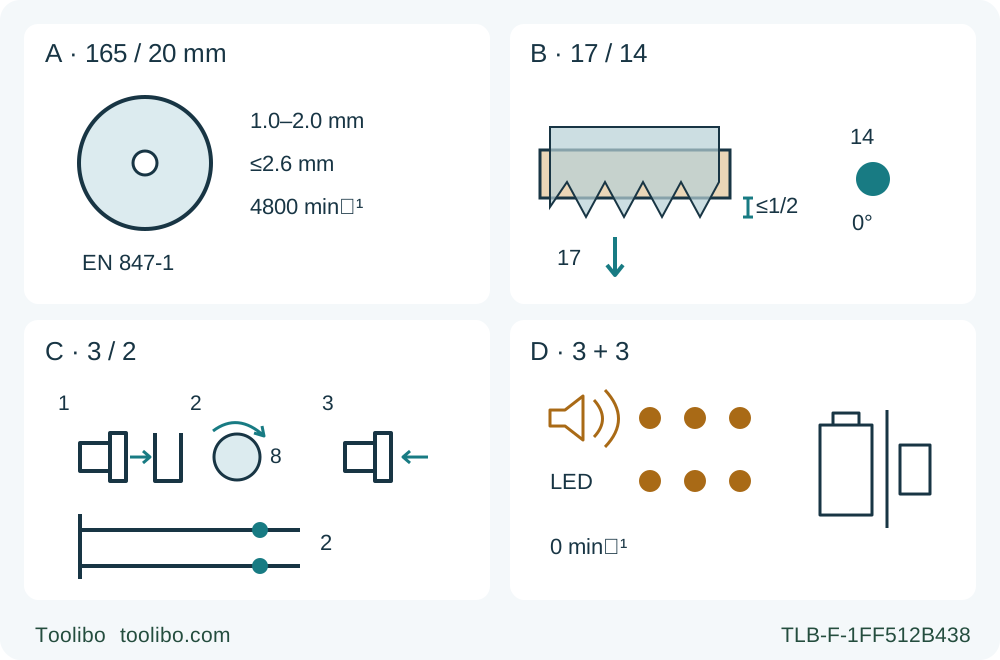
A · Retain the exact original assembly
Verify the original 165 x 20 mm EU wood blade, 1.0–2.0 mm body, maximum 2.6 mm kerf, EN 847-1 and suitability for 4800 rpm; uncertain fit stops the task.
B · Set isolated depth and square angle
Remove the battery, set no more than half-tooth projection, push lever 17 fully down and independently secure zero bevel with screw 14.
C · Lock nozzle and fence separately
Push connector 3 in, rotate and pull out into a locked index; secure both fence levers 2 and verify the hose and fence through the entire isolated rehearsal.
D · Recognize, stop and assess
Three beeps and three tool-LED flashes identify the documented kickback-related shutdown. Release the trigger, await standstill and isolate for assessment; the diagram gives no recovery procedure.
This is a controls and qualification aid, not an assembly or running-cut diagram. A does not authorize flange conversion. B is adjusted only with the battery removed, and lever 17 must be fully down after setting. C separates the indexed nozzle sequence from the two fence clamps; the edge-following fence rail, not the transverse bars, is parallel to the blade. D recognizes the current documented warning only: it does not instruct a test, reset or restart. The three marks in each row of D represent successive beeps or successive flashes of the single tool LED, not three separate lamps or their physical colour.
This workflow qualifies a KS 18 LTX 66 BL for one ordinary, square, edge-start cut in known clean wood. It uses the EU machine identity 11866000 and manufacturer instructions 17027689_00_0526, together with the separate general safety instructions. Match your actual tool, supplied documents and visible controls before proceeding. The current document includes a kickback-related shutdown signal; an older description that omits it is not the reference for this task.
The outcome is a measured, supported sample with secure depth and fence settings, a clear extraction route and an understood stopping decision. It is not a flange-conversion, blade-fitting, rail-commissioning or protection-reset lesson. Although the general guard warnings mention special cuts, the specific intended-use section says this saw is not designed for plunge cuts. Start at an accessible edge, not inside a panel.
1. Admit the original assembly and the actual power system
Keep the correctly installed original EU wood-cutting assembly. The table specifies a 165 mm blade with a 20 mm mounting hole, a body thickness from 1.0 to 2.0 mm and a maximum cutting width of 2.6 mm. The blade must suit the saw’s 4800 rpm no-load speed, the material and the markings on the machine. The instructions require genuine Metabo blades; wood blades must conform to EN 847-1. A cracked, distorted, blunt, unidentified or incorrectly fitted blade is a stop condition, not something a slower feed can fix. HSS blades and abrasive wheels are not alternatives.
The manual describes a two-sided inner flange, including a 5/8 in face. That description is not permission to substitute a different bore, flip an unknown assembly or adapt this EU machine by eye. If the installed blade, flange orientation or fastening history cannot be established, stop for the complete matching instructions and competent correction. This workflow gives no abbreviated replacement sequence or guessed tightening force.
Use an already commissioned genuine 18 V power system whose actual pack and charger instructions you possess. The illustrated genuine LiHD packs are 625368000 at 5.5 Ah, 625369000 at 8 Ah and 625549000 at 10 Ah. Select your already qualified listed pack; do not infer that a shared connector approves every battery or charger. The manual recommends at least 5.5 Ah for performance, rather than declaring that value an absolute safety minimum. There is no new charger setup or charging-indicator tutorial here. Begin with a sound, adequately charged pack under its own complete instructions; an unknown pairing, damaged casing, leakage or unexplained abnormal heat prevents admission.
2. Build a supported cut before attaching the battery
Remove the battery by its release button and keep it separate from the saw throughout inspection, adjustment and rehearsal. A released trigger, lock button or dark LED is not electrical isolation. Confirm the switch is off before any later insertion.
Choose a manageable wood sample with a straight reference edge. Inspect it for nails, screws and hidden contamination. Mark the retained dimension and the waste side. Use firm support and clamps so the piece cannot slide, rock or drop into the blade. For a panel, support both sides near the cut and near the outer edges, without putting any support in the blade’s path. Think through the last centimetres: the offcut must not twist, pinch the kerf or pull the retained piece away, and the saw’s base must remain supported on the retained portion. Do not hold the stock in your free hand or balance it across your leg.
Wear eye and hearing protection and suitable respiratory protection for the dust, with effective source extraction and ventilation. Keep other people away from the discharge and cutting area. Remove loose clothing and secure hair. Check the entire route, including the underside, clamp handles, workbench fittings and the space needed for the saw to clear the far edge. A line that looks unobstructed from above may still intersect a support below.
3. Check the guard, then set half-tooth depth and zero bevel
With the battery removed and the blade stationary, check that the lower guard moves freely and closes immediately. It must not touch the blade or other parts at all angles and depths of cut. A dropped tool, damaged guard, weak return, sticking or accumulated debris that prevents correct closure requires correction before operation. Never tie or clamp the guard open. For this ordinary edge-entry cut it operates automatically; its retracting lever is not a control to hold open through the cut.
Support the base on the sample and loosen depth locking lever 17. Set the depth for the actual stock, using scale 18 only as a starting reference. The working instruction and figure call for no more than half of a tooth to project beneath the material. Inspect actual projection rather than choosing maximum depth or assuming the scale proves it. Push lever 17 all the way down again and verify the setting does not shift.
The bevel control is locking screw 14. This body does not inherit the two bevel locks of another Metabo saw. With power isolated, set the base and motor section to the square position, check the indication and tighten the screw. The separate undercut button 13 permits settings beyond 45 degrees and is automatically deactivated at the next adjustment; it is not needed for this square task. Leave the factory angle-adjustment screws alone. If the secured setting does not produce a square sample, stop to diagnose under the complete instructions rather than calibrating during a live cut.
4. Lock the extraction route and both fence clamps
Set connector 3 with the battery removed: push it fully inward, rotate to the suitable position, then pull it outward to engage a locked position. There are eight indexed positions. Confirm it cannot freely turn; a nozzle resting between positions is not secured. Connect a suitable extraction unit and suction hose for the material. Route the hose so it cannot catch the lower guard, cross the cut, lift the base or pull the saw sideways at the far end. No free-air vacuum headline or unspecified adapter is accepted as proof of a working installation.
For this sample, use the actual matched parallel stop against the straight stock edge. It can enter the provided supports from either side, but both clamping levers 2 must secure it. The edge-following fence rail must be parallel to the blade; the transverse support bars are not supposed to run in the blade’s direction. Read mark 15 for an initial width and establish the actual result with a test cut. Do not treat the printed scale as a finished-width guarantee.
The left, red-marked edge of cutting indicator 12 is the square-cut reference. The right edge is for 45 degrees. Keep this distinction separate from the fence-width mark. Set the sample to leave the intended waste allowance, and check the blade path rather than steering halfway between the two indicator edges. This task does not establish compatibility with any guide or mitre rail merely because the base has grooves.
5. Rehearse the whole path, then make one sample
While still isolated, rehearse the travel with the base supported, keeping the blade clear of the material and supports. Confirm that both handles remain accessible, both fence clamps and the depth and bevel locks remain secure, and the hose can follow without becoming taut. Do not drag the blade through the stock to simulate cutting. Resolve every obstruction before power is attached.
Move the saw to the starting position with the blade clear of the work. With the switch off, insert the qualified battery until it engages. Start the connected extraction in accordance with its own instructions. Grip the saw with both hands, one on each intended handle, and keep your body out of line with the blade. Push locking button 6 forward and hold it, then operate trigger 5. Let the blade reach full speed before entering the edge.
Feed straight at a steady rate without forcing, twisting or levering the saw sideways. Keep the base and fence contact stable and let the lower guard operate automatically. Do not reach underneath, rearrange a support or adjust the fence while running. For a normal completed cut, continue until the blade has cleared the work, then release the trigger. Wait for complete standstill before withdrawing or setting down, and require the lower guard to cover the blade. Do not turn an ordinary finish into an early trigger release while the blade is still cutting.
If the blade binds or anything becomes abnormal, the normal finish instruction does not apply: release the trigger immediately and hold the saw motionless until the blade stops. Do not pull a turning blade backward or lift it out. Remove the battery before inspecting the cause. This is a stop-and-assess boundary, not a restart recipe.
6. Read the current warning signals without treating them as clearance
The 0526 manual describes kickback-related shutdown accompanied by three beeps and three flashes of the tool LED. Release the trigger and allow complete standstill. The function cannot prevent every kickback or replace sound support and straight feeding. Never provoke a kickback to test it, and never interpret a cleared light as proof that the work or tool is ready.
Other protective conditions are different. A continuous warning beep may accompany automatic protection and ends when the trigger is released or after a maximum of 30 seconds. A flashing single battery indicator denotes a nearly empty pack. Prolonged overload can reduce performance through temperature protection, and excessive overheating can shut the machine down. Do not keep pressing the trigger against an unresolved load, jam or thermal condition.
This bounded sample workflow stops after an unexpected shutdown for isolated assessment of the blade, guard, support, kerf, hose and settings. The full manual contains further cause-specific instructions; omitting a restart procedure here does not mean the manufacturer universally requires service after every signal. Use those complete instructions and competent assistance when the cause or condition is uncertain. Electrical repairs belong to qualified personnel, not to this sample exercise.
7. Accept the result, not merely the completed cut
After standstill, guard closure and battery removal, measure the retained width at both ends and check squareness against a known reference. Examine whether the fence stayed in contact, the base remained supported and the kerf stayed open through separation. Burning, severe tear-out, a changing width, new vibration, a shifted lock or a snagging hose is a reason to withhold acceptance and correct the cause, not to repeat the same setup faster.
Record the actual pack identity, blade qualification, stock thickness, half-tooth depth, square indicator edge and measured sample width. If anything that affects geometry changes, recheck it with another sample before cutting valued stock. Vacuum accumulated dust and the ventilation openings with the battery removed; do not blow or sweep harmful dust into the air. Confirm the guard is still free, store the isolated saw securely and keep the battery under its own storage instructions. A successful sample qualifies this verified setup, not every material, angle, accessory or protection-recovery task.
Models referenced