
Four unplugged setup checks
Four control diagrams show half-tooth projection, two bevel screws and separate 47-degree stop, the right-entering rip fence, and a screw-secured extraction adapter.
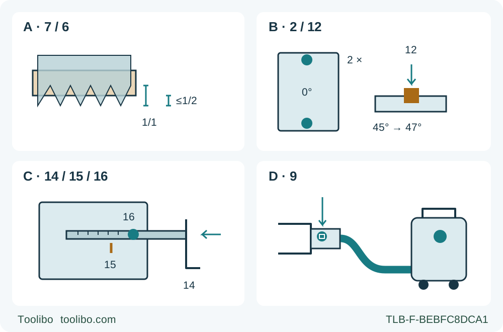
A · Depth 7 / 6
Set depth with screw 7 and scale 6, then verify no more than half a tooth below the real workpiece and lock securely.
B · Bevel 2 / 12
Set and lock both screws 2 at zero; stop 12 extends the range when pushed down and is not an angle lock.
C · Fence 14 / 15 / 16
Insert fence 14 from the right, read at mark 15, lock screw 16 and prove exact width on scrap.
D · Extraction 9
Secure adapter 9 with its socket-head screw and connect suitable extraction; route the hose clear of the guard and travel.
An isolated controls checklist, not an installation drawing or a running cut. A compares a whole tooth with the recommended maximum half-tooth projection. B separates both bevel locks from the downward 47° limit stop; the sample remains at zero. C shows the documented fence insertion side, reading mark and lock, not blade handedness. D requires the adapter screw and a suitable connected extractor.
A square-cut setup for the KS 55 FS you already own
The useful result of this guide is a supported, square wood sample that confirms the depth lock, both bevel locks, guide setting and dust connection on an existing Metabo KS 55 FS. It is not a blade-fitting lesson or a demonstration of every capacity printed on the box. A readable depth scale is only one part of that result: the actual tooth projection, a stable workpiece and a guide that stays fixed must agree with it.
This workflow is tied to type 00955… / service identity 00955000 and the manufacturer’s 0526 operating instructions. The same booklet also covers the KS 55, but the two names are not interchangeable: its overview identifies the rail guideway and rail-play screws as KS 55 FS features. We will use a clamped straightedge or the documented rip fence, not commission a guide rail. Read the complete operating booklet and the separate general safety instructions supplied with your machine before using it. If your controls or identification do not match, stop and obtain the correct documents.
Establish the original assembly and power conditions first
Begin with the plug physically disconnected. The starting condition is an already correctly fitted, undamaged, material-appropriate wood blade with the original matched mounting hardware. The specification table gives a 160 mm blade, 20 mm bore, maximum 1.4 mm blade-body thickness and 2.2 mm cutting width; it lists 5,600 rpm no-load speed. These are identification and compatibility checks, not permission to assemble a replacement from loosely matching dimensions. A wood blade must meet EN 847-1 and be suitable for the saw’s no-load speed. Do not use a cracked, distorted or blunt blade, an HSS blade, a grinding wheel, or improvised bore adaptation.
If the blade’s identity, washer arrangement, seating or fastening is uncertain, do not perform a trial cut to find out whether it works. Resolve the complete assembly against the exact instructions, or have it corrected by a qualified service provider. This article intentionally does not extract a few blade-change steps from that larger procedure. The spindle-lock button is not an operating brake and must only be pressed when the motor is at a standstill.
Read both voltage and frequency from the actual rating plate and match the supply; do not infer either from the model name or the shape of a photograph’s plug. The operating instructions require an upstream RCD with a maximum 30 mA trip current. Check the cord and plug for damage, keep connections dry, and use an appropriate outdoor extension when working outside. Damaged electrical equipment is a stop condition, not something an RCD makes acceptable. Keep the switch off while connecting power, and leave the saw unplugged throughout all setup checks.
Choose a sample that lets the saw remain supported
Use a sufficiently large, flat piece of known untreated wood or wood-based material suited to the installed blade. Check for nails, screws and other foreign objects. Exclude tiny pieces, installed walls, concealed services, unknown coatings and hazardous materials. This is an edge-start cut, not an internal opening: the specified-use section expressly says this machine is not designed for plunge cuts. Generic lower-guard warning language elsewhere in the booklet does not change that restriction.
Clamp the work to a stable platform. Support the retained piece and arrange the offcut so that it cannot sag into the blade and close the kerf. For large panels, support near the cut on both sides and near the outer edges. Check underneath the entire line for the blade’s clearance from supports, clamps and the floor. Never use a leg or a free hand as work support. Plan to keep the guide plate supported on the retained material throughout the cut, including the exit.
Wear eye and hearing protection, use respiratory protection appropriate to the material and exposure, and provide ventilation and suitable source extraction. Wood dust is not harmless simply because the stock is untreated. Keep other people out of the cutting and dust area. Arrange a stable stance with your body beside, rather than directly in line with, the blade and with both hands available for the saw’s main and auxiliary handles.
Set depth by the tooth, then lock it
With the plug out, loosen depth locking screw 7. Raise or lower the motor section relative to guide plate 8, using scale 6 as a starting reference. Tighten screw 7 again. For this workflow, use the manual’s more specific recommendation: no more than half of a tooth should project below the actual workpiece. Its general safety section also requires less than a full tooth; the half-tooth setting satisfies that broader limit rather than replacing it with a deeper cut.
Check projection against the real stock thickness without putting fingers in the cutting path. A nominal sheet thickness or a remembered scale setting is not sufficient. Then check that the depth remains fixed under an isolated handling rehearsal. If the lock does not hold reliably, stop. The manual includes a lever-position adjustment, but this first-use article does not turn an unreliable lock into a novice repair exercise.
Recognize two bevel locks and a separate 47° stop
There are two bevel locking screws, both numbered 2 in the overview. Loosen both to set the motor section against the guide plate, read the angle on scale 3, and tighten both again. For the sample, set zero and verify a square blade-to-base relationship without contacting the teeth. A secure front screw does not compensate for an unsecured rear screw.
The separate undercut limit stop 12 extends the available bevel range from 45° to 47° when pushed down. It is not the bevel clamp, not a depth selector and not something to press for an ordinary square cut. Knowing what it does prevents an unfamiliar extra control from being treated as a lock. Leave angled cutting, zero-stop calibration and rail-play adjustment outside this square-sample workflow. If the actual zero setting is inconsistent, resolve that condition before cutting rather than correcting the result by steering the running saw.
Fit extraction and establish the guide line
The extraction adapter 9 must be secured with its socket-head screw. Connect a suitable extraction unit and suction hose to that adapter, checking the actual mating parts rather than assuming that a convenient hose diameter proves compatibility. Support the hose so it cannot tug the saw sideways, foul the lower guard or catch a clamp during the whole travel. This guide uses extraction for the wood sample. The manual separately says to remove the adapter when extraction is not being used; leaving a disconnected adapter in place is not an alternative dust-control method.
For a straightedge, clamp a straight, sound guide to the work and guide the plate along it. Determine the required blade-to-guide offset with an isolated measurement and a scrap trial, not a dimension copied from a different saw. Confirm that the base, motor, guard and hose can clear both clamps. The cutting indicator 13 helps follow a marked line, but do not infer a particular kerf edge or a zero-clearance accuracy promise from its name.
For a rip parallel to a reliable straight stock edge, the rip fence 14 inserts from the right-hand side into its support. Read its setting at mark 15 and tighten locking screw 16. The manufacturer recommends a test cut to establish the exact width. Check that the fence remains against the reference edge without forcing the saw sideways. A damaged or wandering reference edge is not corrected by tightening the fence harder. Use a rip fence or straightedge for ripping; do not substitute freehand steering.
Rehearse isolated, then make one controlled sample
Before reconnecting power, move through the intended route with the blade clear of the material. Check that the main and auxiliary grips remain usable, the cord and hose stay out of the path, and the guide plate remains supported. Inspect the lower guard with the prescribed retracting handle: it must move freely, close instantly and avoid the blade and other parts at all angles and depths of cut. Never tie or clamp it open. If the guard or its spring is sluggish, bent or damaged, stop for correction before use.
Place the saw for an edge start with its base supported and blade clear of the work. Reconnect only after the settings and surroundings are ready. To start, press and hold locking button 5, then operate trigger 4. Let the blade reach full speed before entering the wood. Keep both hands on the saw, maintain contact with the guide and feed without forcing. Do not reach beneath the work, remove chips, adjust a clamp or reposition the hose while the blade is moving.
For a normal through-cut, complete the cut with the blade clear of the work before releasing the trigger, while retaining support and control. The manual says not to switch on or off with the blade touching the work. Wait for complete standstill before lifting the saw from the cutting position; check that the guard covers the blade before setting it down. There is no stopping-time guarantee in this workflow.
Binding or an interrupted cut is different from normal completion. Release the trigger immediately and hold the saw motionless until the blade stops. Do not pull it backwards or lift it out while moving. Unplug it before investigating support movement, a closing kerf, blade condition or a shifted setting. Do not keep trying starts in a jam or use force to finish a failed sample.
Accept the result, not just the cut edge
After disconnecting power, check the sample’s width and squareness, and inspect the cut for obvious burning, excessive tearing or signs of binding. Recheck that depth, both bevel screws and the selected guide setting stayed secure. A dimensional miss calls for an isolated measurement and a new scrap test, not an improvised adjustment during the next live cut. Any unexplained vibration, guard interference, lock movement or electrical problem rejects the setup even if the edge looks straight.
Clean the work area with suitable dust collection rather than stirring settled dust into the air. Keep the motor ventilation openings clean, and follow the manufacturer’s isolated maintenance instructions for the guard. Do not treat cleaning as authorization to dismantle the guard or make electrical repairs. The manufacturer reserves electrical repairs for qualified electricians and specifies a special original replacement mains cable. Store the disconnected saw with its blade guarded and the cord protected. The finished outcome is a documented, repeatable square-cut setup—not a claim that the machine’s rail, bevel and service procedures have also been learned.
Models referenced