
Four checks specific to the KSE 55 Vario Plus
Four controls panels show service identity and actual voltage/frequency with 30 mA protection; motor lock 20 distinct from stop controls 21, 22 and 23; front-to-rear guide locks with a downward fence; and wood dial 6 with separate starting and overload lamp contexts.
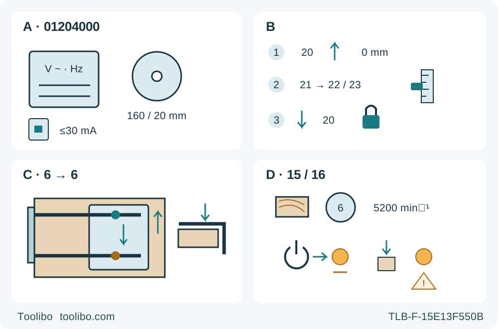
A · Qualify the exact tool
Match 01204000, actual voltage/frequency and upstream RCD ≤30 mA; retain the qualified original 160/20 mm assembly and clutch maintenance gate.
B · Preselect, lower, lock
Release 20 and raise to zero; release 21, set 22 on 23 and reclamp; lower to the stop and retighten 20. Verify no more than half a tooth below the wood.
C · Fence and lock order
For a straight workpiece edge, face the fence rail down and set that rail parallel to the blade; tighten front guide screw 6 then rear 6.
D · Speed and signal context
Wheel 15 at 6 gives about 5,200 rpm no-load for the selected wood. Signal 16 is briefly lit at startup but indicates overload if it lights during operation.
A disconnected controls diagram, not a running-cut plan or blade-fitting procedure. A assumes the original correctly maintained clutch/blade assembly; diameter and bore alone are not enough. B separates motor lock 20 from stop lever 21, stop 22 and scale 23. C shows the front-then-rear tightening order and downward edge-following fence, without a blade-handedness claim. D distinguishes a brief starting indication from overload during use; dial 6 is the documented solid-wood/plywood setting, not a feed-speed promise.
A repeatable wood setting needs both depth controls
The Metabo KSE 55 Vario Plus has a preselected depth stop and a separate motor-section lock. Setting one does not finish the job of the other. This existing-owner workflow uses that distinction to prepare a supported, square, parallel cut in known untreated wood, then checks the result before repeating it.
The exact identity is service entry 01204000 and the KSE 55 Vario Plus family marked 01204.. in instruction manual 17026863, revision 0419. The current service entry also supplies general safety instructions 17030000, revision 1025. Read both complete documents and match the actual tool, controls, voltage and frequency. This is not a new-kit promise or permission to substitute another Metabo circular saw’s adjustment sequence.
Keep the outcome narrow: an ordinary edge-start wood cut with the existing correctly maintained original blade assembly, automatic lower guard and supplied-style double parallel stop. No internal plunge, rail operation, wall-guided cut, plastics or metal is taught here. Those other uses require their own complete equipment and instructions, not an extension of the sample below.
Establish the assembly and electrical prerequisites
Switch off and unplug before checking or changing settings. The documented blade envelope is 160 mm diameter and 20 mm bore; the table lists 1.4 mm maximum blade-body thickness and 2.2 mm cutting width. Use an approved, sharp, undamaged wood blade meeting the manual’s requirements, including suitability for the maximum 5,200 rpm no-load speed and EN 847-1. The diameter and bore alone do not qualify an unknown blade or mounting arrangement.
There is a particularly important reason not to turn this owner guide into an abbreviated blade-change recipe. The safety clutch depends on the correct assembly condition: the manual specifies a thin film of a particular multipurpose grease on the blade-fixing screw’s blade-contact surface. A generic instruction to degrease every contact surface would conflict with this model’s requirement. Equally, that fact is not permission to oil arbitrary parts or estimate a replacement torque. Start only with an original, correctly fitted and maintained assembly. If its history or condition is uncertain, stop and use the complete exact instructions and qualified service before operating.
The S-automatic clutch limits the drive effect when the tool jams or catches, but the manual still warns of substantial forces. It is not an electronic lift-detection system, an immunity claim or a reason to test the saw by deliberately jamming it. Both-hand control, stable footing and correct support remain essential.
Match the mains voltage and frequency to the actual rating label. The manual requires an upstream residual-current device with a maximum trip current of 30 mA. Neither a service-page regional description nor the shape of a plug establishes the supply at your bench. Check the cord, plug and handles; use only an appropriate, undamaged extension when necessary. A damaged mains cable requires the specified original replacement through the proper service route, not an improvised splice.
Qualify guard, material and support
With the plug disconnected, check that the movable lower guard travels freely and returns automatically, easily and fully. Its retracting lever must not be used to tie it open. Inspect for damage, debris or a spring problem at all angles and depths of cut. If the guard does not close immediately or touches the blade or another part, have the fault corrected before use.
Select dry, known, untreated wood with a straight reference edge. Inspect it for nails and other foreign objects and remove them. Do not use a very small piece that would need to be held in the hand. Secure the work to a stable platform and support the retained portion beneath the base. For larger panels, support both sides near the cut and near the outside edges to prevent sagging and kerf closure. Keep bench parts and clamps out of the complete blade path, and let the waste separate without trapping the blade.
Arrange suitable extraction at the source, ventilation and appropriate eye, hearing and respiratory protection for the material. For extraction, the manual says to connect a suitable extractor and suction hose to the machine, removing chip nozzle 9 if necessary. It does not establish a universal hose diameter. Confirm the actual compatible connection without obstructing the guard or travel. A rotated chip-ejection nozzle directs chips; it does not itself collect dust. For this workflow, establish the suitable extraction arrangement before cutting.
Set the depth in the model’s actual sequence
Use the numbers in the manual’s overview, not numbers from a parts-catalogue diagram. Locking screw 20 holds the motor section at its working depth. Lever 21 clamps stop 22 against scale 23. They are separate functions.
With power unplugged:
- Release locking screw 20 and lift the motor section relative to the guide plate to the zero-depth position.
- Release clamping lever 21. Move stop 22 to the desired depth on scale 23, then clamp lever 21 again.
- Lower the motor section until it reaches the stop.
- Tighten locking screw 20 again, then verify the actual blade projection for the stock.
Metabo recommends no more than half of each tooth projecting below the workpiece. That also stays within the general safety instruction requiring less than a full tooth. Use the real tooth geometry and board thickness to check the result; a remembered number on the scale is not enough. The preselected stop does not authorize leaving screw 20 loose for an ordinary edge-start cut.
If the locking mechanism does not hold properly, do not compensate with excessive force or start reindexing the lever from this guide. The manual describes a separate adjustment, but uncertain locking is a service or complete-instruction issue before use. Changing stock thickness requires a new depth check, even when the width setting is unchanged.
Set square bevel and the double parallel stop
Loosen both bevel locking screws 5, establish zero bevel, then retighten the front screw followed by the rear screw. Check that the base and motor section are secure. This is not the same as using only the more accessible front screw. If the resulting sample is not square after the ordinary setting and support checks, do not turn it into an unplanned blade-angle calibration procedure.
For a cut parallel to the workpiece’s straight outer edge, fit the parallel stop with its edge-following rail facing down. The manual also describes an upward-facing arrangement for a guide edge on the workpiece; that is a different reference and is not used in this sample. Do not reverse the fence merely to make an obstructed layout fit.
The double parallel guide can enter from either side of the base. Set its edge-following rail parallel to the blade, then tighten the front guide screw 6 followed by the rear screw 6. The two transverse support bars are not supposed to run parallel to the blade: the parallel relationship concerns the fence rail that follows the workpiece edge. Check that the fence remains squarely seated and cannot shift after tightening.
Use a test cut to establish the actual width. The cutting indicator 2 corresponds to the blade’s left cutting edge; it is not a universal centre-of-kerf mark. Mark the retained boundary and identify the waste side, rather than allowing the cut width to consume the desired dimension. The overview illustration is a controls diagram, not a claim about the operator’s handedness or an instruction to stand directly behind the blade.
Select wood speed and distinguish the signal contexts
The speed wheel is control 15. The source table recommends setting 6 for solid wood and plywood; that corresponds to approximately 5,200 rpm no-load speed. This is a selected operating speed, not a measured feed rate or permission to force the saw through resistance. This wood-only workflow does not transfer the setting to plastics or metal.
The signal display 16 lights briefly at switch-on to indicate readiness. Illumination during operation indicates overload, for which the manual directs reducing the load. These two contexts are different; a brief starting indication is not the same as a persistent warning under load. Nor does the lamp prove physical isolation or replace attention to sound, vibration and feed.
If overload appears, ease the load rather than pushing harder. If the warning persists, the blade binds, or behaviour is abnormal, release the trigger and stop to investigate after standstill and disconnection. Do not repeatedly restart into an unresolved fault or try to demonstrate the clutch’s limit.
Rehearse, cut and stop without losing support
With the saw unplugged, check the approach, base support, fence engagement and clearance through the whole cut. Route the mains cable so it cannot snag or enter the cutting area; the tool’s cable guide 14 can help manage it. Keep the extraction hose clear too. Both hands must remain available for main handle 24 and auxiliary handle 25, with balanced footing and the body to one side of the blade’s line.
Connect power only after setup is complete and the trigger is released. Place the base securely with the blade clear of the work. Press and hold locking button 7, then actuate trigger 8. Let the blade reach full speed before entering the wood. Keep the base flat, the fence following its straight reference and the feed smooth; never twist a running blade back toward a missed line.
For the normal finish, continue the supported travel until the blade has cleared the work, then release the trigger. This respects the manual’s instruction not to switch on or off while the blade touches the workpiece. The emergency binding rule is different: release immediately and hold the saw motionless until the blade stops. Never pull a moving blade backward out of the kerf. Unplug before correcting support, depth, guide alignment or debris.
Wait for complete standstill and confirm lower-guard coverage before setting the saw down. Do not use the spindle lock or side pressure to stop a rotating blade. After disconnection, measure the sample width at both ends and check its square edge. Accept it only if the result and the unchanged support, clamps and locked settings all pass. Vacuum accessible dust and ventilation openings; avoid dispersing settled dust by casual sweeping or blowing. Record the successful stop, fence and stock settings, and repeat the sample after a relevant change.
Models referenced