
F identity, tooth projection, front controls and separate lighting
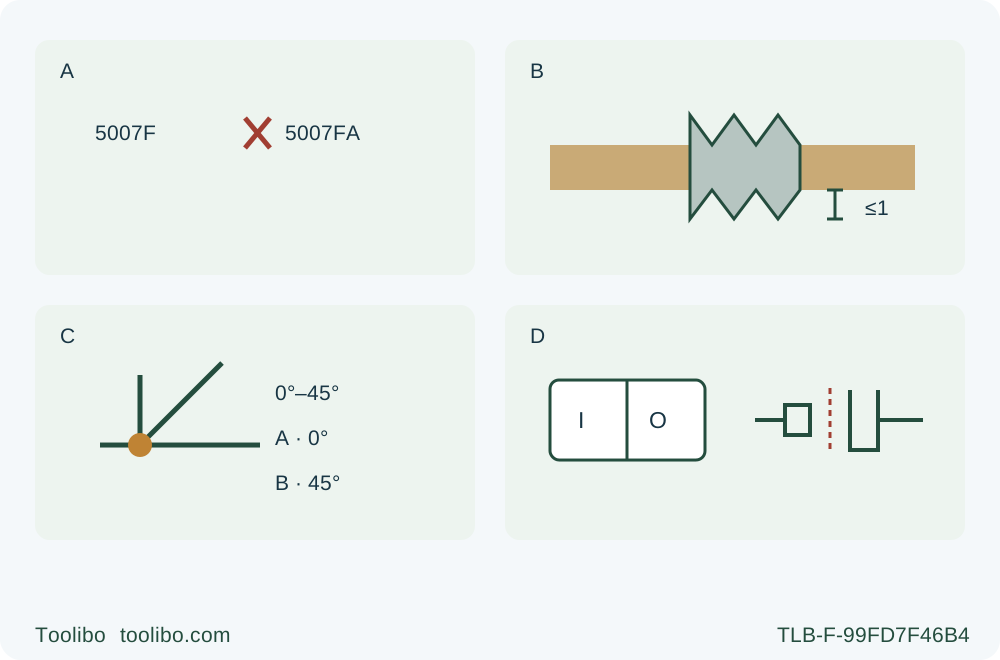
A distinguishes 5007F from 5007FA; B shows the documented maximum one-tooth projection; C shows front bevel range and A square/B 45 references; D separates the lamp switch from a physically disconnected connector.
A · Keep the exact F identity
Match 5007F and 884404A 949; do not import FA electric braking, 5008 dimensions or MG positive-stop mechanics.
B · Set real stock depth while isolated
Unplug, adjust with the rear depth lever and secure it. The manual permits no more than one tooth; use less than a full tooth for this sample and verify underside clearance.
C · Lock square bevel and use A
With power disconnected, set zero with the front clamping screw and tighten it. Use A rather than B, then verify the actual blade/guide relationship on scrap.
D · Separate light, stop and isolation
Use the lamp’s own switch and keep it off when finished. Lamp state does not prove standstill or disconnection; wait for full stop and guard closure, then unplug for inspection.
A marks different model identity, not a defect in either model: the electric-brake section applies to FA models, not 5007F. B depicts the manual maximum of one tooth; the body chooses less than a full tooth for this sample. C recognizes the 0–45-degree control range but teaches only zero-bevel use, with A for square cuts. D is conceptual: the separate lamp ON/OFF control does not isolate the tool; adjustments require the plug physically disconnected. No blade-fitting or live-cut layout is shown.
The 5007F has a separate lamp switch, a rear depth lever and a front bevel clamping screw. Its shared instruction manual also contains electric-brake instructions—but those apply to the 5007FA and 5008FA, not to this 5007F. A useful first owner sample therefore starts by identifying the actual controls, not by assuming that another saw with a similar name works the same way.
This workflow covers an existing US 5007F matching manual 884404A949, its actual nameplate and a correctly installed original approved wood-cutting assembly. The current US product page links that shared North American manual, whose back page names Makita Canada; that link establishes the document relationship, not a claim that every regional tool or old carton is identical. The task is one supported, square, edge-start cut in known clean wood, followed by measurement and an isolated inspection. No blade replacement, supply conversion, internal service or bevel project is included.
Match the machine and retain the qualified original blade
Read the full model on the tool. Do not transfer the 5008F blade size, the FA brake or the magnesium-body 5007MG stop arrangement. The 5007F specification row gives a 185 mm / 7-1/4 in blade and 5800 rpm no-load speed. The current US product identifies a 5/8 in arbor. Keep the actual correctly fitted original blade, washers and bolt whose dimensions, speed suitability and wood-cutting purpose have already been established for this machine.
If the blade markings, flange relationship or previous fitting are uncertain, stop for the complete matching instructions and competent correction. A different blade with a familiar outside diameter is not automatically suitable, and a common model family does not authorize a different regional bore. Cracks, distortion, missing teeth, damaged mounting parts or a blade that has become unsuitable for the material prevent this sample. This guide does not supply a partial removal sequence or a guessed torque.
The current product lists blade D-45989-1, but that does not prove what an older owner received or fitted. Nor is advertising about a framing blade evidence that this exercise should cut nail-embedded lumber: the operating safety instructions require inspecting for and removing nails. Select clean, known wood. Weight figures differ between the current listing and shared manual, so they are not used to make a handling or performance claim here.
Qualify the supply and separate lighting from isolation
Use the tool only with a supply that matches its actual electrical nameplate and complete instructions, in a dry, suitable work area. The US listing states 15 A; the nameplate and the manual’s extension-cord table govern the actual setup. A cord must be sound and adequately sized for its length and the tool load. If the supply or extension choice is uncertain, resolve that before operation rather than trying an available lead and judging by whether the motor starts. Do not alter the plug. This workflow does not teach a generator, DC connection or voltage conversion from the product’s AC/DC marketing phrase.
Switch off and physically unplug before inspection, adjustment or rehearsal. Check the entire supply cord, plug and tool entry for damage. Do not use a damaged cord or a switch that fails to control the machine. The trigger should move properly and return to OFF when released; check this while unplugged before later connecting power. There is no additional lock-off action to invent from another model.
Locate the separate lamp switch while isolated. Its ON side lights the lamp and its OFF side turns it off when power is available. Do not confuse it with the motor trigger. The lamp does not prove the blade is stopped, and an extinguished lamp does not prove the plug is disconnected. Do not stare into the light source. Keep the lamp switched off when the saw is not being used, as the manual directs.
Inspect the guard and plan the entire supported cut
With the blade stationary and plug removed, use the retracting lever to check that the lower guard moves freely and closes immediately when released. It must not touch the blade or other parts at all angles and depths of cut, and the retracting lever must not strike the housing. Check the spring action. A dropped saw, bent guard, sticking mechanism or failed return requires correction before use. Cleaning or a new blade does not replace this check.
Never clamp or tie the guard open. For the ordinary edge-entry cut in this workflow, the workpiece opens it automatically and it must return normally after the cut. The retracting lever is not a handle to hold throughout a straight cut. Keep hands away from the teeth and never reach beneath the material while operating.
Choose a manageable sample with a sound straight reference edge. Mark the retained dimension and the waste. Clamp the sample on a stable platform so it cannot rock or slide; do not hold a short piece in your hand or across your leg. Support the retained portion near the cutting area, keeping every support out of the blade path. For a panel, provide appropriate support near the cut on both sides and near its edges so sagging does not close the kerf. No fixed support spacing or overhang capacity is assumed.
Put the wider portion of the base on the supported retained wood, not on the piece that will fall away. Think through the final separation: the waste must not trap the blade or pull the main piece out of position. If the base loses stable support before the blade clears the edge, the setup is not ready.
Lock actual depth and square bevel independently
Keep the saw unplugged. Release the lever on the rear depth guide and move the base relative to the body to suit the real stock thickness. The exact manual specifies no more than one blade tooth below the workpiece; for this sample, choose less than a full tooth of actual projection, then tighten the lever securely. Check the underside clearance and verify that the secured depth does not shift. A printed scale and a thin-looking board are not substitutes for checking real projection.
The front bevel scale plate is secured by a clamping screw. Loosen that screw, set the base to the square position and tighten it securely. The documented adjustment range is 0–45 degrees, but this exercise remains at zero. It does not use the 5007MG’s separate positive-stop arrangement or any 56-degree setting. Confirm the depth and bevel locks separately; securing one does not secure the other.
At the front of the base, the A sight position is for a straight square cut and B is for 45 degrees. Use A for this task, but still establish where the actual blade removes material on a sample. The guide mark is an alignment aid, not a finished-dimension guarantee. Do not place the blade halfway between A and B or treat a brighter lamp as evidence that the kerf is on the correct side.
Choose the guide, then rehearse without power
For ripping, use a rip fence or straightedge guide. If the exact matched guide rule is already qualified, bring its edge-following face snugly against the straight stock edge and secure it with the screw at the front of the base, while unplugged. Check that its parts do not interfere with the blade or lower guard. Do not substitute an arbitrary fence because its bar appears to enter the slot.
Alternatively, clamp a suitable straightedge and position it using a verified sample offset for the actual blade, base contact side and square setting. This is not permission to mount the saw on an unverified rail system. Make the guide long and stable enough to control entry and exit, and place clamp handles clear of the moving base, housing and cord. If the desired sample cannot be guided without an obstruction, change the layout before plugging in.
Wear eye and hearing protection and suitable respiratory protection for the dust. Maintain ventilation and appropriate dust controls without improvised attachments that impair guard movement. The built-in blower clears the line; it does not collect hazardous dust. Clear other people from the working area and keep clothing and hair away from moving parts.
Rehearse the complete path with the plug removed, both intended grips accessible and the blade clear of the wood. Check the whole cable route, not just the short length near the handle. It must not cross the cutting path or snag a clamp or board corner near the exit. Confirm the underside remains clear and the retained base support continues. Do not drag teeth through the material as a substitute for this clearance check.
Make one controlled trial and wait for actual standstill
Set the base on the work at the starting point without blade contact. Confirm the motor trigger is OFF, then connect to the already qualified supply. If needed, use the separate lamp switch to illuminate the work without looking into the source. Do not make mechanical adjustments while connected; if the line or setting needs changing, switch off and unplug again.
Grip the front grip and rear handle with both hands, with your body to the side rather than in line with the blade. Pull the trigger and wait for full speed before entering the wood. Advance forward gently and uniformly, keeping the base flat and guide contact steady. Do not force a slowing blade, twist the saw back onto a missed line or reach for the waste. Let the guard operate automatically.
Complete the cut with continued support, release the trigger and maintain control while the blade coasts to a complete stop. The brake paragraphs for FA models are not instructions for this F model, and no fixed stopping time is promised. Require both actual standstill and lower-guard coverage before setting the saw down. Switch the lamp off when finished and unplug before handling the cut piece, moving clamps or inspecting the result.
If the blade binds or the cut departs from the intended path, release the trigger and hold the saw motionless until it stops. Never pull a rotating blade backward or steer against resistance. Unplug before finding the cause. The manual describes further operating responses, but this bounded first sample does not teach restart inside a kerf. Unexplained vibration, noise, switch behavior or guard failure prevents another attempt until correctly resolved.
Accept the measured setup and store it isolated
Once stopped, guarded and unplugged, measure the retained width at more than one point and check the cut square to the chosen reference and through the stock thickness. Look for burning, excessive tearing, a shifted guide or a setting that moved. Confirm that the cord followed freely and that support remained sound at the final separation. A piece cut to the desired width is not an acceptable trial if the guard stuck or the base tipped.
Record the blade identity, actual stock thickness, depth, zero-bevel setting, A sight reference and guide contact side. Changes to the blade, guide or geometry require renewed sample verification. If the result is not square, diagnose the supported setup before seeking the complete prescribed calibration or service; do not adjust factory screws while guessing at a moving guide problem.
With power disconnected, keep the base, grips and guard area free of debris according to the complete instructions. Do not turn the manual’s blade-cleaning chemistry or brush-maintenance sections into a partial service routine. Qualified repair is required where the condition demands it. Leave the lamp off, the saw unplugged and the guarded blade protected during storage. This acceptance applies to the verified square wood setup, not to every material or capability mentioned elsewhere in a shared product family.
Models referenced