
Four isolated XSH04 checks
A shows detached power and original 165 mm/5/8-inch assembly. B separates front bevel lever, rear clamping screw and stopper. C distinguishes partial tooth and right zero reference. D shows already qualified native extraction.
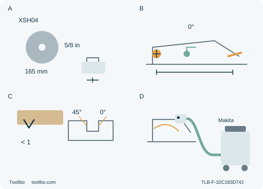
A · Qualify the original system
Original US 165 mm/5/8-inch wood assembly and rating; already commissioned BL1850B/DC18RC only, with the battery removed for setup.
B · Distinguish locks and stopper
With battery removed, front bevel lever AND rear clamping screw secure zero. The separate angle stopper does not lock the base.
C · Verify depth and reference
Actual through-cut with less than a full tooth; lock the depth lever and verify support clearance. Use the actual right zero reference, not a borrowed offset.
D · Require active native extraction
Already qualified screw-secured nozzle/hose/Makita extractor; isolated connection checks, active extraction before cutting, no wireless or retrofit recipe.
Original conceptual controls, not to scale or a fitting sequence. A does not teach charging or blade installation. B requires both bevel fasteners secure at zero; the stopper is separate. C requires actual through-cut with less than a full tooth and clear supports; the right zero reference is not a guide offset. D is an already correctly installed nozzle/hose/Makita extractor, isolated during connection checks and active during cutting. No XSH05 wireless function is depicted.
The US Makita XSH04 combines a compact 165 mm blade with two bevel fasteners, a separate angle stopper and automatic speed-change indication. None of those features makes the tool ready merely because a battery fits. This workflow qualifies an existing, correctly assembled wood-cutting system and finishes one modest, supported square crosscut, followed by an isolated inspection of the result.
It applies to an actual XSH04 matched to instruction manual 885646-948, XSH04-1, dated 20180130. The current US XSH04ZB product links this shared XSH04/XSH05 manual, but the wireless-activation sections are explicitly for XSH05 only. A package suffix is not another mechanical model. Do not transfer another country’s bore, an XSH05 wireless procedure or an apparent equivalent model’s controls to this saw.
1. Establish the complete existing system
Start with the original approved, correctly installed wood blade and mounting hardware already qualified for this actual US tool: 165 mm diameter and the US 5/8-inch arbor arrangement. The blade’s speed rating must meet or exceed the speed marked on the tool; the documented no-load speed is 5000/min. A matching diameter alone does not establish approval, correct washers, flange orientation or tightening. The manual includes country-dependent mounting branches; this guide does not select a ring, fit a blade or resolve an uncertain assembly. Unreadable markings, an unidentified substitute or doubtful hardware mean HOLD for qualified correction before power is connected.
Inspect the isolated original blade for dullness, damage and contamination, and the accessible tool for loose or damaged parts, binding, misalignment and a bent base. Keep cutting edges sharp and clean under the complete maintenance instructions. Do not diagnose abnormal vibration with a powered trial or use the sample to prove an uncertain assembly safe. A damaged tool or battery must be assessed before use.
Use only the owner’s already commissioned genuine BL1850B battery and DC18RC charger system, with their complete applicable instructions available. Both identifiers appear in the saw’s permitted lists; this is not a promise that the pictured or purchased package includes them. Charging, battery repair, cold-battery warm-up cuts and electrical troubleshooting are outside this task. An unknown, modified, damaged or leaking pack is not a candidate for a test cut. Protect detached terminals from metal objects. Do not store the tool or battery where temperatures may reach 50°C/122°F; that storage limit is not a new operating or charging-temperature rule.
A complete native dust arrangement is another prerequisite: the correct screw-secured dust nozzle and hose connection to a suitable Makita vacuum must already be properly installed and qualified under the actual instructions. This guide does not retrofit a nozzle or invent a universal hose diameter, adapter or suction threshold. If that complete system cannot be established, stop before cutting rather than substituting a loose hose beside the blade.
2. Isolate and inspect the guard and switch
Release the trigger, wait for complete blade standstill and switch the tool off before removing the battery. Hold the tool and cartridge securely, slide the button on the front of the cartridge and withdraw it. A lamp going dark, a brake response or an indicator state is not physical isolation. Keep the battery separate while inspecting, setting depth or angle, positioning the guide and checking the hose.
Before every use, check that the lower guard moves freely and closes immediately. With the battery removed, operate its retracting handle as the manual directs, release it and observe closure. Verify clearance from the blade and every other part at all angles and depths of cut, and that the retracting handle does not touch the housing. Inspect spring operation. Never clamp or tie the guard open. Damage, sluggish motion, deposits that obstruct closure or uncertain spring action require service before use, not a live guard test. Recheck the final selected setting after adjustment. For this ordinary edge-entry cut, the guard must operate automatically; there is no reason to hold it open manually.
Check the trigger while isolated: it must operate properly and return to OFF when released. The lock-off must remain intact. Known operation from the trigger alone without the lock-off requires qualified service; do not energize the tool to reproduce that fault. Do not pull the trigger hard without first operating the lock-off. Remove setup keys or tools before reconnecting power.
3. Prepare a manageable stock and support arrangement
Choose sound, dry, known solid wood approved for the existing blade, with enough retained material to support the wider part of the base throughout the cut. Inspect the entire route and remaining stock for nails and other foreign material. Exclude unknown treated or coated material, hidden services, metal, masonry and an installed building component. This is not a maximum-depth or large-panel challenge.
Work in a clean, well-lit, dry place, with the tool protected from rain and wet conditions and no explosive atmosphere of flammable liquids, gases or dust. Keep children and bystanders away. Wear ANSI Z87.1 eye protection, hearing protection and appropriate respiratory protection; the saw’s additional warnings require a dust mask and hearing protection. Ventilation and active extraction must suit the actual wood dust and surroundings. Do not wear cloth work gloves that can catch in moving parts, loose clothing or jewellery. Keep hair clear. Users of pacemakers or similar devices should obtain the device maker’s or doctor’s advice before operating this tool.
Clamp the retained work securely to a stable platform. Support the future offcut independently outside the blade path so it can separate without falling onto the blade or closing the kerf. Do not clamp across the separation or hold either piece by hand. Supports, clamp bodies and jaws must remain clear of the blade below the stock, the full base travel, both handles and the moving guard. Never reach underneath or behind the saw.
Mark the wanted end and the waste side from a trustworthy reference. If using a clamped straightedge, establish the actual base-to-cut relationship on matched scrap rather than borrowing another saw’s offset. The guide must remain rigid and clear of the motor, guard and hose. Check the whole travel and exit from a stable stance with the battery removed, blade covered and no tooth contact; rehearse beside or safely above the intended route, not by forcing the projecting blade through uncut wood. If either hand must leave its handle, the base loses support or the hose will snag, redesign the support before proceeding.
4. Set zero and actual depth separately
With the battery removed, loosen the front bevel lever and the rear clamping screw, bring the base to zero and securely tighten both. The angle stopper selects the permitted bevel range; it does not replace either locking point. This task stays at zero and does not teach high-angle cutting or alignment-screw calibration. If the existing square setting cannot be confirmed, obtain qualified correction rather than compensating with a crooked guide.
Release the depth-guide lever, set a through-cut for the actual stock and tighten the lever securely. The scale is a guide, not acceptance evidence. Inspect the real blade projection with safe support and no hand in the tooth path: the blade must cut through while less than a full tooth is visible below the work. Confirm clearance from every support and clamp underneath. Recheck depth after angle changes and before cutting; a nominal capacity or scale reading never overrides the actual partial-tooth limit.
For a straight cut use the actual zero-degree position on the front base. In the manual’s sighting view, the zero reference is to the right of the 45-degree reference. That location is not a factory guide offset or a guarantee of the finished dimension. Check the marked line, waste side, guide contact and full supported exit together. The finished sample will verify the result, not silently correct an uncertain setup.
5. Connect only after all static gates pass
Keep the saw off with its battery removed and isolate the extractor under its own instructions while checking or connecting the existing hose. Confirm that the nozzle is secure and the hose cannot restrict the guard or pull the tool sideways at entry, mid-cut or exit. Activate and check the qualified extractor according to its instructions before cutting; a connected but inactive hose is not dust control. XSH04 has no permission here to use the XSH05 wireless-activation procedure.
With the trigger released and the tool off, align the battery tongue with the housing groove and slide it fully home until it clicks. The red indicator must no longer be visible; otherwise the battery is not locked completely. Do not force insertion. Stop if the pack, latch or actual pairing does not match the qualified system.
Hold the rear handle and front grip firmly with both hands, using the insulated gripping surfaces where relevant to electrical contact hazards. Keep hands away from the cutting area, underside, blade and chip path, without interfering with guard movement. Stand to either side of the blade line, not directly behind it. Put the base flat on the supported retained work with the blade clear of the stock. Operate the lock-off and pull and hold the trigger; wait for full speed before contact. Feed straight forward smoothly with the base flat and the guide contact maintained. Do not force the saw until speed falls, twist it toward a wandering line or reach to catch the offcut.
6. Recognize signals without inventing a mode or reset
The speed-change indicator describes the tool’s automatic response: unlit indicates high-speed mode, steady green high-torque mode and flashing green overload alert. It is not a user speed selector, a reason to press harder or a measurement of available cutting force. An overload or protection shutdown is not permission to keep the trigger held while manipulating the tool. Release it, keep the saw controlled until full standstill, isolate and have the cause resolved under the complete instructions. This guide does not supply a reset sequence or a cold-pack warm-up routine.
Do not stare into the lamp. Its afterglow is not a blade-stop indicator or an isolation check, and there is no energized lamp demonstration in this workflow. The electric brake can react immediately, so maintain a firm hold when releasing the trigger. If the tool consistently fails to stop the blade quickly after release, the manual requires Makita service. No elapsed-second estimate replaces observation of complete standstill, and the brake never replaces the lower guard.
7. Finish, inspect and decide
After the planned clear exit, release the trigger and retain both-hand control until the blade has stopped completely and the lower guard covers it before setting the saw down. Remove the battery before measuring, touching the cut pieces, checking the setup or handling the hose. Do not grasp waste while the blade is moving.
Binding, interruption or a wandering cut is a different condition: release the trigger and hold the saw motionless in the material until complete stop. Do not withdraw a moving blade or pull the saw backward. Isolate before investigating; do not force a trapped tool out or restart in the old kerf using this guide. A support, guide, blade or alignment fault must be resolved before considering another separately planned cut.
Inspect both faces and the cut edge after isolation. Check the marked dimension from the original reference, square end, straight edge, tear-out, burning and whether the guide or clamps moved. A small cosmetic defect is not evidence that a loose blade or binding episode was harmless. Accept this sample only when the actual result meets the stated project requirement and the tool, guard, support, extraction and controls behaved normally. Otherwise record the failure and hold the work for qualified correction or a revised safe layout, rather than trimming a small loose offcut to rescue it.
Keep guards and accessible surfaces clear under the complete maintenance instructions. This guide does not teach compressed-air internal cleaning, alignment adjustment, blade fitting or battery repair. Do not use gasoline, benzine, thinner, alcohol or similar cleaning agents. Store the isolated tool and protected battery securely away from children. The completed outcome is a checked sample and a documented ready-or-hold decision for this exact system, not certification of every later cut.
Models referenced