
Four isolated checks for a single-pack XSH03
A shows one detached 18 V pack; B a round-bore 165 mm / 15.88 mm original blade; C separate rear depth and front zero-bevel controls; D a matched nozzle, supplied replacement guard lever, mounting screw and hose.
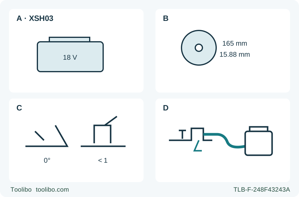
A · Remove and qualify the single pack
Switch off and remove the battery for setup. Use an actual listed genuine pack already commissioned with its approved charger; on later installation the red indicator must be hidden.
B · Retain the original US assembly
Confirm the original correct 165 mm blade and 15.88 mm US mounting arrangement. No 20 mm regional substitution or abbreviated bolt procedure is provided.
C · Lock depth and zero bevel separately
Secure the rear depth lever at less-than-full-tooth projection and the front bevel lever at zero. The 45/50 stop changes range, not cutting depth.
D · Verify the whole extraction assembly
The nozzle requires its supplied replacement lower-guard lever and securing screw. Use an already correct matched system, then verify guard return and hose clearance before work.
All panels describe battery-removed inspection, not a running cut. A requires an actual manual-listed genuine pack and separately established charger approval. B retains the correct installed assembly rather than teaching replacement. C separates depth and front bevel; actual projection is less than a full tooth. D identifies an already correctly fitted accessory system: nozzle, its supplied replacement lower-guard lever and mounting screw, plus the matching vacuum hose. It does not teach the retrofit or authorize a generic nozzle.
The US XSH03 is a single-battery saw whose high-speed and high-torque modes are selected automatically by load. Its mode lamp is not a speed-selector switch, its work lights are not proof of blade movement, and an extraction nozzle is not a stand-alone universal fitting. Those distinctions matter when preparing one controlled square wood cut.
This guide follows the US XSH03 and manufacturer manual 885374A945 / XSH03-1, currently linked from the XSH03Z product page. Use the complete instructions matching the actual tool and accessories. The outcome is a supported, zero-degree sample with the original correctly fitted US wood blade, a qualified single battery, and a checked dust-control arrangement. No DHS680 equivalence, new blade fitting, rail adapter, charger commissioning or protection-lock reset is taught.
Keep the original US blade and a genuinely matched power system
The linked manual specifies a 165 mm blade, 5000 rpm no-load speed and one 18 V battery. The current US product specifies a 5/8 in arbor, and the manual’s actual flange drawing marks 15.88 mm. Do not substitute a 20 mm blade or a different regional flange arrangement because a visually similar Makita body exists elsewhere. Confirm the original blade is sound, suited to the wood and correctly mounted with the actual supplied parts and direction markings.
This is an already assembled owner workflow. The manual’s clockwise removal and counterclockwise tightening of the blade bolt are not reproduced as a partial replacement recipe. Do not loosen the bolt, reverse a flange, add a reducing ring, improvise torque or use a guessed wrench for the sample. If the installed blade or clamp arrangement is uncertain, stop and resolve it with the full matched instructions and suitable service. A blade requiring removal for cleaning also falls outside this setup task.
The manual explicitly lists BL1815N, BL1820, BL1830, BL1840 and BL1850. Use an actual genuine listed pack that has already been commissioned with its manufacturer-approved charger under complete owner instructions. The current product discusses wider Star-system compatibility, but this bounded task does not use that marketing sentence to expand the older manual’s list. Do not infer a charger model or kit contents from the tool’s battery slot.
The pack must be undamaged, ready and appropriate for the actual system. If charging instructions or approval are missing, establish them before using this workflow. Do not attempt charging from this article, use a damaged pack or expose the terminals to loose metal. Avoid wet conditions and storage where the tool or battery may reach or exceed 50 °C / 122 °F. Abnormally short operating time is a reason to stop and investigate, not to keep cycling a suspect battery.
Remove the battery and check the starting and guarding controls
Switch off before installing or removing the battery. Hold both tool and pack securely, operate the battery button and slide the pack out; leave it separate during inspection and all setup. A released trigger, mode change or protective stop is not physical isolation.
With the pack removed, check that the trigger operates correctly and returns to OFF when released. Identify the lock-off lever and do not force the trigger against it. During normal use, starting requires pressing the lock-off and pulling the trigger. If the motor can run simply by pulling the trigger without the lock-off, stop using the saw and have it repaired as the manual directs. Never tape down or defeat that control.
Check the lower guard before each use using its retracting handle. It must move freely, avoid the blade and other parts at all angles and depths of cut, and close promptly when released. Confirm the retracting handle does not strike the housing. A slow spring, damaged guard, accumulated debris or exposed blade after release rejects the tool for use until corrected. For this ordinary edge-entry cut, allow the guard to operate automatically; do not tie it open.
Inspect the wood as carefully as the saw. Use dry, sound, untreated stock with no nails, screws or unknown coating. The manual limits the tool to wood products; abrasive wheels and an assumed nonwood application are excluded. A loose board or panel is not an installed wall or floor with hidden services underneath.
Set depth and zero bevel without confusing the stop range
Keep the battery out. Loosen the lever beside the rear handle, move the base to the required depth and tighten the lever securely. Check projection against the actual stock thickness. The general safety instructions require less than a full tooth below the work; the setup paragraph says no more than one. Use the stricter less-than-full-tooth condition for the actual sample, not an exactly full-tooth allowance.
The maximum 57 mm zero-degree capacity is not the default depth for a thinner board. Excess projection increases exposure and makes the setup less forgiving. Verify the base cannot shift after tightening, and recheck depth whenever material thickness changes.
Loosen the front bevel lever, set zero degrees and tighten it securely. The separate stopper limits the available range: fully counterclockwise is the 0–45 degree range, clockwise permits 0–50 degrees. It does not set the cutting depth or substitute for locking the front lever. This article recognizes the mechanism but performs no bevel cut or high-angle calibration.
Use the zero-degree front sight mark for the square sample, not the separate 45-degree mark. Check the intended square relationship with an appropriate square against the blade body while avoiding the teeth. The manual describes separate accuracy and guide adjustments, but this task does not reproduce their screws or procedures. A faulty alignment or lock must be corrected under the complete instructions before cutting.
Treat extraction as a complete matched assembly
The optional Makita nozzle arrangement has an important prerequisite: the manual requires replacing the lower-guard lever with the lever supplied with the nozzle before the screw-mounted nozzle and vacuum hose are used. A nozzle that seems to fit is not enough. The guard-related component is part of the intended arrangement.
For an extracted sample, use an already correctly commissioned actual Makita nozzle, its supplied replacement lever and secure mounting screw, with a matching Makita vacuum connection. Verify that this complete assembly is present and that the guard still passes its return and clearance checks. This guide does not teach the lever retrofit or authorize a generic nozzle. If the proper accessory set is absent or its installation is uncertain, pause and obtain the full matched fitting instructions rather than omitting a guard part.
Connect the suitable extractor for the selected wood dust and arrange its hose so it cannot snag the work, supports, clamps or saw through the full travel. Do not transfer a Bosch pressure/flow requirement or assume an unlisted hose diameter. Dust extraction does not remove the need for ventilation, eye protection, hearing protection and suitable respiratory protection.
Plan the guide, retained support and offcut before energizing
Mark the finished dimension and waste side. For a rip, use a properly secured straight-edge guide; the manual also describes an optional rip fence, but its inclusion is not assumed here. Establish the actual base-to-cut offset on scrap with the installed blade, then position and clamp the straightedge accordingly. The zero mark helps aim, but it does not replace a measured kerf and guide offset.
Clamp the work to a stable platform, with support near the cut. For a large panel, provide support on both sides near the cut and near the panel edges, keeping every support and fastener outside the actual blade path. The wider base must stay over solidly supported retained material, not the piece that will separate and fall. Arrange waste support so it will not sag into the kerf, twist the blade or require someone to catch it.
The current US product explicitly identifies this as a blade-left design. That geometry does not prescribe where to place a hand: both hands belong on the front grip and rear handle, the body stays to the side of the blade line, and no hand supports stock or reaches beneath it. Select a manageable sample with a clear entry and exit rather than a narrow strip that is difficult to support.
Keep the hook snapped closed during the task. Before installing the battery, rehearse the whole path with the tool isolated: base support, guide contact, guard movement, two-grip access and hose slack through exit. Clamp handles must not obstruct the saw or require a mid-cut reach. Correct any interference now.
Read the indicators without treating them as permission to push harder
The automatic system changes between high-speed and high-torque operation according to workload. A lit mode indicator means high-torque mode; it is not an instruction to select or force that mode. The battery-capacity display and protective indications are separate information, not substitutes for judging the cut.
Overload or overheating can stop the motor, and repeated protection events can lead to a protection lock. Do not try to defeat a stop by repeated triggering, force a stalled cut or use this guide as a reset recipe. Release the trigger, retain control until standstill, remove the battery before assessment, and resolve the cause using the actual tool and power-system instructions. A protection feature does not make a jammed blade or unstable support safe.
The work lights can illuminate when the trigger is pulled without pressing the lock-off. They remain lit for approximately 10–15 seconds after release. Therefore light alone proves neither motor operation nor isolation. Do not use the trigger as an inspection lamp while hands are near the blade, and do not wait for darkness instead of checking actual standstill.
Make the sample and accept both accuracy and control
After the isolated checks pass, keep the switch off and fingers clear of the trigger. Align the ready listed battery’s tongue with the housing groove and slide it fully in until it locks. The red indicator above the release button must no longer be visible. If it remains visible, installation is incomplete. Do not force a pack that does not slide easily or hold it in position while running.
Place the base on the work with the blade clear. Hold the front grip and rear handle firmly, press the lock-off lever and pull the trigger, then wait for full speed before advancing. Feed forward in a straight line, keeping the base flat and the rate steady. Do not twist the saw or force it back toward a wandering pencil line.
If the line is lost, release the trigger and wait for the blade to stop before withdrawing and reconsidering the cut. If binding occurs, hold the saw motionless in the material until complete standstill; never pull a moving blade backwards. Remove the battery before investigating support, guide or blade problems. No interrupted-kerf restart sequence is supplied here.
At normal completion, release the trigger, maintain control and wait for actual standstill. Confirm the lower guard covers the blade before setting the saw down. The product’s electric-brake feature supplies no fixed clearance timer in this workflow. Do not touch waste while the blade is moving.
Remove the battery before measurement or adjustment. Check retained width at several points, straightness, squareness, edge quality and burn marks. Separately assess whether the guide moved, the offcut tipped, the guard hesitated, the hose snagged or protection interrupted the cut. Correct any problem while isolated and repeat on scrap; a neat edge does not excuse a rejected process.
Clean the guard area and ventilation openings under the complete maintenance instructions. If using compressed air as described, wear proper eye and breathing protection. Do not use the prohibited solvents or substitute surface cleaning for the guard-return check. Store the isolated tool securely; if the hook is used between tasks, the manual requires battery removal and prohibits high or unstable hanging. The finished result is a verified single-pack wood-cutting setup, not a new charger, nozzle retrofit or blade installation.
Models referenced