
Four isolated system checks
A identifies HS7600 and original D-45989. B distinguishes rear depth lever and front clamping screw. C selects the actual 0° sight reference. D recognizes the existing nozzle, screw and replacement guard lever with extractor and disconnected supply.
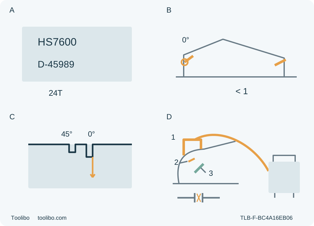
A · Match the actual original system
HS7600 and supplied 885371-941 must match; original D-45989 wood assembly already qualified. No similar-model or new fitting transfer.
B · Separate the two locking controls
Unplugged rear lever fixes actual strict partial-tooth depth; front clamping screw fixes zero. Both must remain secure through the sample.
C · Use the actual zero reference
Align the 0° front sight reference with the qualified line. The supported sample establishes real line and angle acceptance, not a promised offset.
D · Require the whole existing dust assembly
Correct replacement lower-guard lever, nozzle, screw and Makita extractor system already established. No hose-only shortcut; isolated connection checks then active extraction.
Original conceptual recognition, not to scale, a retrofit or a live cut. B requires actual through-cut with less than a full tooth below stock; the front control is a clamping screw, not another model’s paired locks. C identifies zero rather than a calibrated offset. D requires the complete already qualified replacement guard lever/nozzle/screw system and active suitable Makita extraction; no partial installation is depicted. All checks and adjustments are OFF, fully stopped and unplugged, with extractor isolated for connection checks.
The US HS7600 remains documented by Makita even though its current product page marks it discontinued. For an existing owner, the useful question is whether the actual original system can make and pass a controlled square wood sample—not whether a similarly named replacement saw looks compatible. This workflow qualifies one modest edge-started crosscut, from the unplugged inspection to the cooled result.
1. Match the original US body and assembly
Match HS7600 on the physical tool and supplied instructions to manual 885371-941 / HS7600-1. This is not an HS7601, HS301 or a regional-equivalence guide. The manual specifies a 185 mm blade, printed as 7¼ inches, and a 5200/min no-load motor speed. The official US flyer identifies the original 24-tooth D-45989 blade and a 5⁄8-inch arbor. These facts identify the retained original system; they do not authorize a blade from another model or establish an invented minimum blade-speed formula.
The original approved wood blade, its correct mounting hardware and its suitability for the actual stock must already be established. Unknown blade identity, a substituted flange or ring, incorrect washers, a loose bolt or uncertainty about prior fitting means HOLD for qualified correction. This article deliberately excludes the manual’s blade-removal and installation procedure. It also excludes calibration screws, brush replacement and internal repairs. A correct diameter alone is not enough to approve an assembly.
Use known, clean, dry, bare loose wood, not an installed structure, treated/coated material or an unknown recovered board. Inspect the proposed cut and remaining stock for nails and other foreign objects. Exclude damaged, unstable or unsuitable material rather than using the saw to find out what is inside. The sample is square and open-ended; no bevel, interior plunge, blind cut, abrasive wheel or nonwood operation is included.
The manual’s maximum depth is a limit, not a suggested first task. Select a piece that the actual owner can support, clamp, reach and separate safely with the installed blade and a shallow, correctly qualified through-cut. A job that requires stretching, an unsupported shoe or an unverified fixture is not made acceptable by fitting within the capacity table.
2. Establish actual power and dust-control conditions
Use the tool’s actual nameplate supply and an already qualified outlet, plug and cord arrangement. The flyer identifies 10.5 A, but it does not replace the physical voltage/frequency check. The manual’s extension table distinguishes supply voltages, total length and current range; do not infer a universal cord choice from this article. If an extension is needed, its complete rating, condition and suitability must be established from the actual nameplate and complete instructions. Do not modify the plug or repair a cord here. A damaged cord, uncertain supply or switch fault requires correction before connection.
Keep the workplace and tool dry, well lit and clear of flammable liquids, gases and explosive dust atmospheres. Route the cord away from sharp edges, heat and the full blade path. Keep children and bystanders outside the area; maintain nonslip footing without overreaching. Secure hair and loose clothing, keep gloves and other entanglement hazards away from moving parts, and keep handles dry and free of grease.
Wear eye protection, hearing protection and the dust mask required by the manual. Ventilation and appropriate material-specific dust precautions are also necessary. Read the material supplier’s safety information; a bare-wood choice does not eliminate wood-dust exposure. Do not position yourself in the stream of chips or ejected dust.
The optional extraction arrangement is not a hose-only attachment. The manual requires a replacement lower-guard lever supplied with the dust nozzle, the nozzle itself and its securing screw before a hose to a Makita vacuum cleaner. For this workflow, that complete original arrangement must already have been correctly established and qualified under the actual tool and extractor instructions. The replacement lever must not obstruct the guard. No part number, hose diameter or retrofit sequence is invented here. Missing or uncertain components, an unsuitable extractor, or inability to provide the dust controls required by the actual task means HOLD—not a blanket permission to rely on personal protection alone.
With the saw OFF, completely stopped and unplugged, and the extractor isolated under its instructions, check the existing connection and hose routing. Confirm the nozzle and screw are secure and the guard is unobstructed. The hose must remain free of the blade, clamps and the operator’s path through the whole cut. Run and check the qualified extractor under its own instructions before cutting; an attached but inactive hose does not qualify as active capture.
3. Complete the isolated guard and control inspection
Before each reconnection, keep the plug out and confirm that the trigger moves correctly and returns to OFF when released. Do not pull it hard without pressing the lock-off button. Remove adjusting keys or wrenches before power connection. Never tape down or defeat the lock-off. If the tool is known to run from the trigger alone without the lock-off, the manual requires Makita service before further use; do not energize it merely to reproduce that fault.
Inspect the accessible original blade, base and mounting condition for dullness, damage, looseness, misalignment or binding. A poorly maintained blade can increase friction and binding even when the nominal size is correct. Do not compensate with extra feed force. A bent base, unexplained vibration or uncertain assembly needs qualified assessment, not a sample cut as a diagnostic test.
Check the lower guard and its spring while unplugged. Open it with the retracting handle, release it and observe immediate free closure. Verify that the retracting handle does not hit the housing and that the guard clears the blade and other parts through all documented cutting angles and depths. After a drop, check for damage as well as unrestricted operation. Deposits, damaged parts or a sluggish spring require correction before use. Do not clamp or tie the guard open. In this ordinary edge-entry task the guard operates automatically; there is no manual hold-open step.
4. Arrange the whole cut, then lock the two settings
Clamp the retained stock securely to stable supports. Support the separating piece independently so that its weight cannot close the kerf, trap the blade or pull the tool. Keep support near the cut and edges as needed to avoid sag, but outside every possible blade path. Waste must remain free to separate; no helper, hand or leg holds it, and nobody reaches beneath the work. Never hold a small loose piece for a recut.
Place the wider part of the base over solidly supported retained stock, not over the portion that will fall away. Qualify the entry, middle and exit: base support, front and rear grip reach, clamp clearance, stable body position and cord/hose travel must remain satisfactory through complete separation. Check reach only beside or safely above the route with the isolated blade guarded and no tooth contact. Do not drag an unplugged projected blade through wood or force the guard open as a rehearsal. If the full route does not close, change to a qualified arrangement or stop.
With the plug disconnected, loosen the rear depth-guide lever, move the base to the required depth, then tighten the lever securely. Verify the actual wood thickness and blade projection, not just a scale reading. The general safety section says less than a full tooth visible below the work; the depth section says no more than one tooth. Use the stricter less-than-full-tooth through-cut condition so both are satisfied. The blade must still cut completely through without touching supports or anything below.
At the front, loosen the separate clamping screw, set the bevel to 0° and tighten it securely. This is not the two-bevel-clamp arrangement of another Makita model. Confirm that neither depth nor bevel can shift. Use the actual 0° front sight reference for the marked square line, rather than the 45° reference. The mark is an alignment aid; qualify its real relationship to the installed blade on this supported sample, with the waste side clearly identified. No factory offset or finish tolerance is assumed, and no adjustment of factory calibration screws is taught.
5. Cut with both designated grips and a clear stop plan
Recheck OFF, full guard coverage, secure settings and original assembly, removed setup tools, clear supports and the operating extractor before connecting the qualified supply. Hold the front grip and rear handle firmly, using insulated gripping surfaces. Keep both hands away from the blade and cutting area, not behind the saw or under the work. Neither hand may impede guard movement. Position your body to either side of the blade line, not directly in it, while maintaining the actual two-grip reach and stable footing.
Set the supported portion of the base on the retained work with the blade clear of its edge. Depress the lock-off button and pull the trigger, holding the trigger during the cut. Let the blade reach full speed before contact. Advance straight and smoothly with the base flat, keeping the original supported route and automatic guard movement clear. Do not force, twist or slow the blade by excessive feed. A line error is not permission to steer sideways through the wood.
On normal completion, release the trigger and wait for actual complete standstill before withdrawing or lifting the saw. Confirm that the guard covers the blade before putting the tool down securely. Then unplug it before handling the result or inspecting settings. This conservative stop-before-withdrawal route avoids any reliance on coast-down timing; no electric brake or stopping interval is assumed.
If the blade binds, the cut is interrupted, support changes or the saw leaves the intended line, release the trigger immediately and hold the saw motionless until the blade stops completely. Never pull a spinning blade backward or lift it out of the material. Disconnect power before assessing the cause. The source’s stop-before-withdrawal instruction for a wrong line is explicit. This article does not teach trapped-tool release, old-kerf restart or an automatic return to use after a fault; an unclear condition requires qualified assistance.
6. Decide whether the sample and system are acceptable
With the saw unplugged and blade cooled, inspect both pieces without touching sharp edges. Check complete separation, actual length and line location, squareness through the thickness, edge straightness and both faces for damage or burn. Confirm that neither part sagged into the kerf, the settings stayed locked and the guard, nozzle, hose and cord remained unobstructed. Geometry alone does not establish a controlled process.
Accept the sample only if the result meets the actual intended job and every setup condition remained sound. A line-reference or ordinary zero-setting adjustment can be reconsidered only with power isolated and the tool otherwise known to be sound, followed by a fresh fully supported sample. Persistent burning, abnormal noise, binding, movement of settings or uncertain guard operation calls for a hold and qualified investigation—not another forceful trial or an improvised calibration.
After use, unplug the tool and keep the upper/lower guard system free from buildup that could interfere with closure. Accessible routine cleaning must follow the complete instructions; this bounded workflow does not reproduce compressed-air blowdown, blade-removal chemical cleaning or internal service. Do not use gasoline, benzine, thinner, alcohol or similar solvents. Unresolved deposits or damage go to appropriate Makita service. Store the cooled tool dry and out of children’s reach, recording its actual document, original assembly, qualified extraction and sample result. A later blade, guard-lever, nozzle or supply change requires renewed qualification, not automatic reuse of this acceptance.
Models referenced