
Recognize the isolated settings without commissioning another assembly
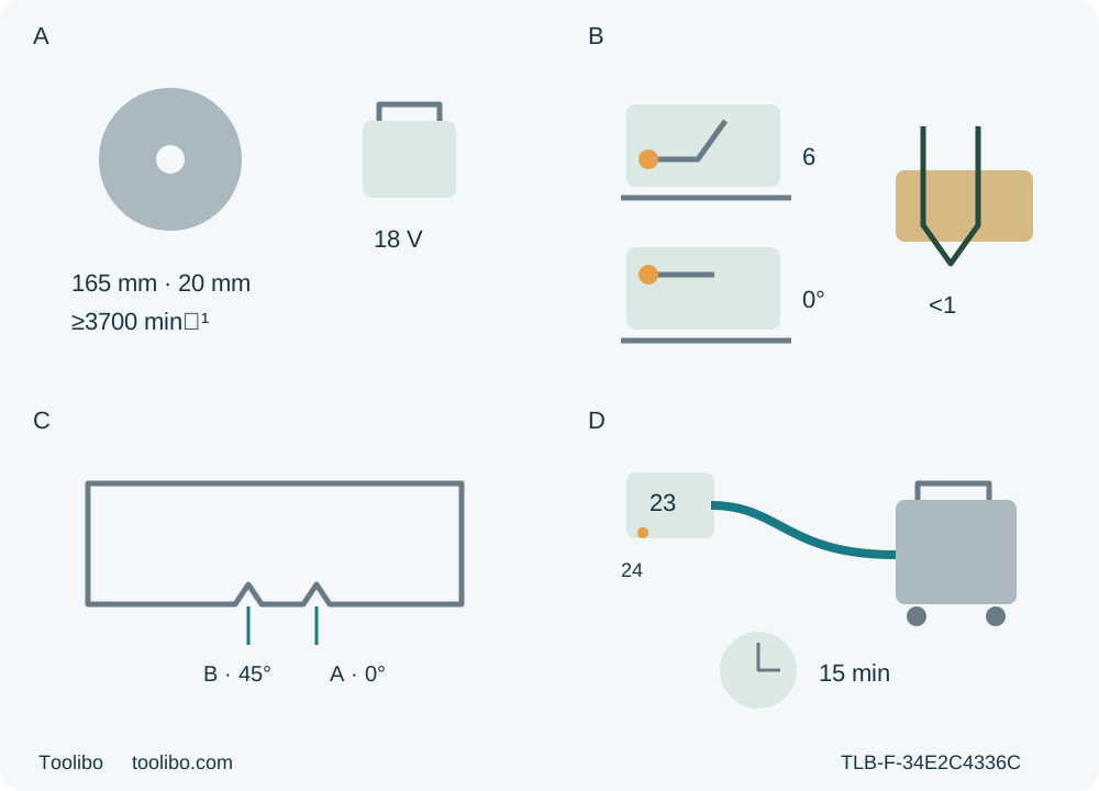
A shows a 165 mm/20 mm original blade rated at least 3700 rpm and detached battery. B separates rear depth and front zero-bevel controls beside a partial tooth. C identifies A for square cuts and B for 45 degrees in the actual front-view arrangement. D shows existing nozzle 23 and screw 24 connected to extraction, with a separate 15-minute tool-rest reminder.
A · Establish the existing UK system
Original approved 165/20 mm blade and correct hardware, rating at least actual 3700 rpm, plus commissioned BL1850B/DC18RC must already be qualified; remove the battery for checks.
B · Separate depth from bevel
Battery out: rear lever 6 sets actual through-cut with less than a full tooth exposed; the independent front bevel lever locks zero. Both must remain secure.
C · Use the square sightline
For this zero-degree sample align A with the cut line; B is the 45-degree reference, not an alternative square offset or a new bevel tutorial.
D · Verify extraction and duty history
Existing nozzle 23/screw 24/hose and actual Makita extractor instructions must close before cutting. If continuous operation discharged the pack, rest the tool 15 minutes before a fresh pack.
Conceptual isolated symbols are not to scale. A does not authorize fitting a blade or a new power pair. B retains strictly less than a full tooth despite the later no-more-than-one wording. C is a sightline identification, not a factory offset. D recognizes an already qualified native arrangement and does not reconstruct missing Figure 29 or equate 26 mm/front cuff 22 to 25/31 mm. The 15-minute rest applies after continuous operation until battery discharge, not every cut or a charging cycle.
This guide takes an existing, correctly qualified UK Makita DSS610 through one supported square crosscut in clean loose wood and an isolated acceptance check. Match the actual tool and supplied instructions to the current 84-page 885250H993 manual reached through Makita UK’s DSS610 manual entry. The same document also covers DSS611, but its different controls and features are not pooled into this workflow.
The task is deliberately narrower than setting up a new saw. Original blade and mounting qualification, an already commissioned BL1850B/DC18RC power system and an already qualified native extraction arrangement must all exist before the sample. If any is unknown, hold and obtain exact instructions or qualified correction rather than using a test cut as approval.
1. Establish the original UK assembly
The UK product identifies a 165 mm blade and 20 mm bore; the manual gives 3700 rpm no-load speed and requires a blade marked for at least the speed marked on the actual tool. Confirm the actual original blade’s identity, manufacturer approval for this tool and wood, correct dimensions, rating and EN 847-1 conformity. Do not infer the supplied blade’s part number from optional blades listed on a product page.
The manual includes country-specific ring and flange arrangements. This workflow retains the original correctly assembled UK system; it does not select a ring, flip a flange, fit another bore or choose bolt direction/torque. A 20 mm headline alone cannot establish the correct actual mounting stack. Unknown history, incorrect or loose hardware, blade wobble, damaged teeth, cracks, distortion, dullness or sticky deposits require correction before use. No blade removal or chemical cleaning recipe is included.
Use the complete supplied tool, battery and charger safety documents, not only the summary here. The current H993 operating authority is the 84-page document; an older 76-page rendering is not assumed to contain its newer dust instructions. No equivalence to a different-market model or a second DSS611 owner is claimed.
2. Confirm commissioned power and the fifteen-minute limit
Use the actual genuine BL1850B pack and DC18RC charger only when they have already been correctly commissioned under their complete matching instructions. Both are listed in H993, but a tool table is not a new charging procedure, a universal pairing chart or a promise about carton contents. The pack should already be appropriately charged and sound. Never use a damaged, altered or non-genuine pack or attempt pack repair.
Keep terminals away from metal objects, water and rain, and keep dust/chips out of battery holes and grooves. Do not store or use the tool or pack where the temperature may reach or exceed 50°C. This prohibition is not a charging-temperature specification. Hot packs and tool terminals can burn; allow appropriate cooling before handling and follow their full instructions. An excessively shortened operating time is a stop condition, not a reason to fit another pack and continue testing.
The tool has overload, overheating and overdischarge protection. Automatic stopping does not mean physical isolation or that the underlying cause is cleared. This guide does not teach reset or energized cooling tests. In particular, if the saw has been operated continuously until the battery is discharged, the manual requires the tool to rest for 15 minutes before proceeding with a fresh battery. That is a tool-rest obligation, not a charging-time promise. A damaged or unexplained system remains on hold after any rest period.
3. Remove the battery and inspect the guard and switch
Release the trigger, wait for complete blade standstill, then hold the tool and pack securely while sliding the pack’s front button and withdrawing the battery fully. Keep it out for checks, settings, extraction connections and measurement. No base-lowering step precedes this removal: lowering the base appears in the separate blade-installation procedure, which is outside this task.
Check the body, base, both grips, original visible mounting hardware and adjustment levers for damage, looseness, binding or misalignment. Before each use, open the lower guard by its retracting handle and release it; it must move freely, close instantly and clear the blade and other parts at all angles and depths of cut, including after a drop. Check the spring and make sure the retracting handle does not strike the tool housing. A sluggish, damaged or non-closing guard requires service before use. Never tie or hold it open for an ordinary cut.
With the battery still removed, check that the trigger actuates properly and returns to OFF when released. Do not pull it hard without pressing the lock-off lever; the manual warns that this can damage the switch. Never tape down or defeat the lock-off. If the saw is already known to run without the lock-off being pressed, stop using it and return it to a Makita service centre; do not recreate that fault under power.
DSS610’s lamp-only description allows light operation without the lock-off, while actual motor starting uses lock-off plus trigger. This is a distinction to understand, not a diagnostic procedure to perform here. Do not use illumination as proof of a sound switch, stare into the light or force the trigger to investigate it. Remove all adjusting keys before reconnecting power and store the hex key in its designated place.
4. Set actual through-cut depth and square bevel
With the battery out, loosen rear depth lever 6 beside the rear handle and move the base up or down. Establish an actual through-cut with less than one full tooth visible below the material, then tighten the lever securely. The later depth paragraph’s “no more than one tooth” does not weaken the stricter safety instruction. Do not rely only on a scale or a universal millimetre projection, and do not touch exposed teeth while checking.
The separate front lever on the bevel scale plate controls angle. Release it, set zero and lock it securely. For DSS610 the stopper’s fully counterclockwise position selects the 0–45-degree range if range selection is needed; this square task does not open the 50-degree range or teach a high-angle cut. Both depth and bevel locks must hold without movement. Factory square calibration is a prerequisite, not an invitation to turn adjustment screws to compensate for a poor sample.
For a straight cut use position A at the front of the base; B is the 45-degree reference. These are line indicators, not a factory straightedge-offset dimension. Confirm the actual A reference and original blade relationship on this tool, rather than copying a mirrored mark from another model. If geometry or settings cannot be established confidently, hold before cutting.
5. Keep the native extraction uncertainty outside the task
This workflow requires an existing correctly installed native nozzle and a suitable active Makita extractor with the complete actual connection and extractor instructions already qualified. The current manual identifies nozzle 23, securing screw 24, front cuff 22 and a 26 mm inner nozzle diameter. The UK product reports 25/31 mm connection dimensions instead. Those statements are not silently treated as identical measurements or used to invent an adapter.
H993 refers to Figures 18 and 29, but the front figure set inspected here ends at Figure 25. Figures 18 and 19 show the native nozzle/hose arrangement; a missing Figure 29 is not reconstructed from another model. Consequently, this guide does not install a new nozzle, select a replacement cuff or assemble an uncertain connection. If the actual existing hardware, complete instructions or suitable performance are missing, obtain Makita clarification and hold the cut.
With the saw battery removed and the extractor isolated under its own instructions, inspect and connect only that qualified arrangement. Confirm secure attachment and a hose route that cannot catch, pull the saw or interfere with the guard, work, supports or grips. Operate and check the extractor before cutting; a hose attached to an idle machine is not effective extraction.
Wear eye protection, hearing protection and a suitable dust mask. Retain the manual’s recommendation for an FFP2 mask or P2 respirator and, for this European scope, an M- or H-class extractor, alongside actual material hazards and local requirements. The extractor’s own maintenance instructions are necessary to keep collection effective. Do not reuse a dust extractor for metalworking with this wood-dust arrangement. No pressure/flow figure, guaranteed capture percentage or “dust-free” result is claimed.
6. Plan support, line and a complete exit
Select clean, dry, uncoated untreated loose wood approved for the original blade. Inspect the entire intended cut and remainder for nails, screws and other foreign material. Exclude installed work, hidden services, unknown coatings and small pieces that cannot be securely supported and clamped. Keep the tool and workplace dry, well lit and clear of bystanders, flammable hazards and loose objects. Stay within trained competence, stable footing and comfortable reach.
Mark a square line from a verified reference edge and identify the retained portion and waste. Clamp the retained work to a stable platform and place the wider base portion on the solidly supported retained side, not on the part that will fall away. Support the waste independently so it can separate without sagging into the blade or pinching the kerf. All supports stay outside the blade path; do not clamp across the cut or hold material with a hand, leg or helper.
Use this as a modest ordinary crosscut, not a rip-fence installation or a rail task. Check the intended line and blade-clear entry, the whole base’s travel, hose path, two-grip reach and complete exit. With the tool isolated and blade covered, assess those clearances beside or safely above the path without tooth contact. Do not force the guard open to drag a stopped blade through stock. If actual support or reach fails, redesign with qualified help or hold; no universal overhang or improvised foam/backer recipe is supplied.
7. Start clear, feed straight and stop completely
After the isolated checks, confirm OFF, align the battery tongue with the housing groove and slide it fully in until it clicks and locks. The red indicator must be hidden and the pack securely seated; do not force a pack that does not slide easily. Activate and confirm the prepared extractor.
Hold rear handle 27 and front grip 28 firmly by their insulated gripping surfaces. Keep your body to either side rather than in the blade line, with no hand, leg or other body part under the base or behind the saw. Both hands remain on the designated grips, away from the cut and underside. Set the supported front base on the work without blade contact and align the A reference with the intended line.
Press lock-off lever 11 and pull trigger 10 while the lock-off is pressed. Wait for full blade speed before contact, then advance gently in a straight line with the base flat and feed uniform. The lower guard operates automatically for this ordinary entry. Do not force or twist the saw, apply lateral braking pressure or turn it back toward a missed line. An uncertain path is not corrected by steering against the blade.
On normal completion, release the trigger, hold control and wait for actual full standstill before removing or setting down the saw. Confirm the guard covers the blade, then remove the battery before inspection or moving supports. The product’s brake listing supplies no safe stopwatch interval. For binding or any interruption, release immediately and hold the saw motionless until the blade stops; do not pull backwards or lift it while moving. Isolate when safely possible and resolve the cause. Old-kerf restart, trapped-tool removal and energized fault demonstrations are outside this workflow.
8. Inspect, record and maintain the bounded system
With the battery out, inspect both faces and the complete edge for full separation, intended size, straightness and square geometry. Measure at appropriate positions rather than judging by the pencil line alone. Check tearing, burning, rubbing, tooth condition, support/clamp movement, dust capture and any abnormal tool behaviour. Use the project’s actual tolerance, not an invented universal accuracy promise. A poor result requires isolated investigation or qualified service—not another forced pass or a loose-offcut recut.
Record actual UK/H993 identity, original blade approval and mounting history, BL1850B/DC18RC commissioning, the existing extraction documents, depth/projection, both locks and sample observations. If a prerequisite remains unknown, the completed outcome is a specific hold and request for documentation or correction.
Keep the tool OFF and battery removed for care. Maintain accessible guard cleanliness under the full instructions with proper eye and breathing protection; persistent debris, binding or a need to dismantle the assembly goes to qualified service. This guide provides no compressed-air, blade-removal or cleaning-chemical recipe. Do not use gasoline, benzine, thinner, alcohol or similar products on the tool. The lamp lens may be wiped with a dry cloth without scratching it. Brush replacement, factory angle adjustment and other repair remain with a Makita Authorized Service Centre. Store the separated system securely and retain the fifteen-minute rest rule whenever continuous discharge has occurred.
Models referenced