
5903R system checks before connecting power
Four diagrams show plate, knife and kerf thickness ordering; two distinct knife gaps; two bevel clamps with B45 left and A0 right; and a screw-mounted dust joint with disconnected power.
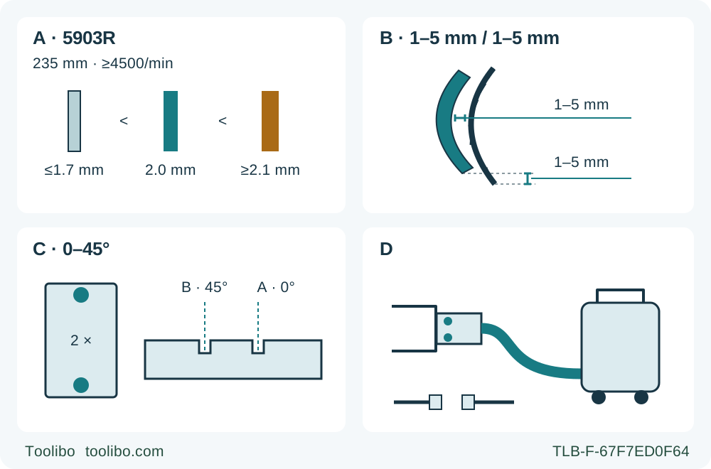
A · Blade / knife / kerf
Confirm the existing 235 mm assembly: plate ≤1.7 mm, knife 2.0 mm, kerf ≥2.1 mm and blade speed rating at least the tool rating of 4,500 rpm.
B · Two clearances
Check both illustrated 1–5 mm relationships; a bent, misaligned or uncertain knife stops this workflow rather than prompting an improvised adjustment.
C · Both clamps and A/B
Lock front and rear bevel clamps at zero for the sample. A is the straight-cut reference; B is for 45° on this model-specific guide.
D · Extraction and isolation
With power disconnected, secure the correct joint using its screws and connect the compatible vacuum hose, clear of the guard and travel.
An isolated qualification diagram, not a blade-fitting or knife-adjustment procedure. A distinguishes blade plate, knife and cutting width. B shows the curved-rim gap and lower-edge distance separately, each 1–5 mm in the source figure. C uses the 5903R top guide, not the other models in the shared booklet. D shows the joint secured by screws and connected to suitable extraction while the saw is disconnected.
Qualify the knife-and-blade system before making the sample
The Makita 5903R is not simply a larger saw with a familiar trigger. Its riving knife makes the installed blade’s plate thickness, cutting width and knife clearance part of the operating setup. This guide brings those checks together with the model’s front-and-rear bevel clamps, A/B sighting guide and screw-mounted dust joint, ending with one supported, edge-start wood sample. The result is an accepted existing-owner setup, not a replacement-blade shopping list or a riving-knife adjustment lesson.
The source is Makita instruction manual 884364M224, dated 2019-03-01. The official download is named 5143R.pdf, but its cover and model-specific sections explicitly include the 5903R. That does not make the 5143R’s 60° bevel mechanism part of this saw. Use this workflow only when your 5903R, its supplied instructions and visible controls match this documented configuration. It is not a claim that this historical booklet is every current regional machine’s latest revision. Read the whole matching manual before operating.
Start with the original approved wood-cutting assembly
Keep the switch off and unplug the saw before inspection or adjustment. This workflow assumes an already correctly installed original 235 mm wood-cutting blade with the correct matched inner flange, outer flange and bolt. It does not authorize changing blade diameter, converting the arbor, substituting washers or following only part of the manual’s fitting procedure. If the installed assembly cannot be positively identified or its condition is uncertain, stop and obtain the complete matching instructions or qualified Makita service assistance.
For the 5903R, the manual specifies a blade plate no thicker than 1.7 mm, a 2.0 mm riving knife and a cutting width of at least 2.1 mm. The plate must therefore be thinner than the knife, while the teeth cut a path wider than the knife. A blade’s outside diameter alone cannot establish that relationship. Do not read 2.1 mm as the plate thickness or borrow another model’s knife thickness from the same table. The blade must be intended for wood, sharp, clean, undamaged and rated at least as fast as the tool’s marked speed; the 5903R table lists 4,500 rpm. The manual additionally requires EN 847-1 blades in European countries.
Do not use abrasive wheels or a blade with damaged or incorrect mounting hardware. Do not press the shaft lock while the saw is running, and do not try to stop a blade by pressing sideways against it. A sample cut is not a safe way to discover whether an uncertain blade fits.
Check both knife clearances without turning this into a repair
The illustrated knife setting has two separate 1–5 mm checks. One is the gap from the knife’s curved leading edge to the blade’s toothed rim. The other concerns how far the toothed rim extends below the knife’s lower edge. The accompanying caution says neither distance may exceed 5 mm. Inspect the actual geometry against the model’s diagram; a single measurement near the top does not verify the lower-edge relationship.
The starting assembly must already have a correctly positioned, aligned and securely fixed knife. If either clearance is outside the illustrated range, if the knife is bent, or if alignment is doubtful, do not loosen its bolt as an experiment. Have the full prescribed adjustment carried out competently and verify the complete system before returning to this workflow. This article does not provide a partial setting recipe or tell you to remove the knife.
The knife can only perform its intended function while engaged in the workpiece. The manual warns that it is ineffective in preventing kickback during short cuts; it is not a universal anti-kickback guarantee. A bent knife can also interfere with the lower guard and slow its closure. Keep the knife installed for this edge-start sample. Plunge cutting and the separate knife-removal exception are outside this guide.
Prepare supply, guard and a stable workpiece
Match the supply voltage to the actual nameplate and use single-phase AC as specified. Do not assume 230 V, 240 V or a regional plug from the model number. The manual always recommends an RCD rated at 30 mA or less and requires RCD protection if operation in a damp location is unavoidable. Prefer a dry working location; protection does not excuse a damaged cord, wet hands or unsuitable connections. Check the cord and plug, and arrange the lead away from the cutting route, heat and sharp edges.
Before plugging in, check that the trigger operates properly and returns to off when released. With the saw still unplugged, inspect the lower guard using its retracting handle. It must move freely and close instantly, without touching the blade or other parts at all angles and depths of cut. Its spring must operate correctly, and the retracting handle must not foul the housing. A sticky, damaged or bent guard rejects the setup. Never tie it open or treat the knife as a substitute for it.
Choose known, untreated wood of sufficient size for stable clamping and support. Remove nails and other foreign objects; avoid tiny pieces, unknown coatings, hidden services and installed construction. Wear eye, hearing and suitable respiratory protection, use dust collection and keep bystanders out of the work area. Do not wear loose clothing or cloth gloves that could become entangled.
Clamp the workpiece securely. Put the wider portion of the base on the solidly supported retained piece, not the piece that will fall away. Support large panels near both sides of the cut and near their edges, arranging the offcut so that it cannot sag and pinch the blade. Confirm clear space below the whole cutting route. Neither a hand nor a leg is an acceptable substitute for a stable platform.
Set the depth and both bevel clamps
Loosen the depth-guide lever, move the base to the required depth and tighten the lever securely. Check actual projection against the workpiece. The functional section says no more than one tooth should project, while the general cutting warnings require less than a full tooth. Use the stricter condition for this sample: less than one full tooth below the wood, with the depth securely locked. Do not maximize depth simply because the capacity table permits it.
For the 5903R, bevel adjustment uses clamping screws at both the front and the back. Loosen both, set the intended angle and secure both again. Its documented range is 0–45°, unlike the 5143R procedure printed alongside it. Keep this sample at zero and check the square relationship before connecting power. A loose rear clamp is not corrected by tightening only the front one. Any shifting setting or unreliable clamp requires correction before use.
Use the model-specific top guide illustrated for 5903R and 5103R. Position A is the straight-cut reference; position B is the 45° reference. In that drawing, B is left of A. The separate 5705R base-plate picture and the 5143R’s four-angle guide are not alternative instructions for the 5903R. For the square sample, use A, then establish the actual cut position on scrap instead of assuming the mark guarantees a finished dimension.
Secure the dust joint and choose a guide
For this wood workflow, connect the documented dust system: fit the joint to the saw using its screws, then attach the hose of a suitable Makita vacuum cleaner to the joint. Confirm that the actual joint, hose and extractor are compatible. The manual does not provide a universal hose diameter or a performance figure to invent here. An optional-accessory list is also not proof that a particular owner’s box contained every listed part.
Arrange the hose and cord so neither pulls the saw sideways, catches a clamp or obstructs the lower guard. Rehearse the whole route with the plug out and blade clear. If extraction cannot be connected correctly, resolve the setup rather than continuing this dust-controlled workflow with an improvised attachment.
For ripping, use the rip fence or a straightedge guide. The documented fence bears against a straight workpiece edge and locks with the screw at the front of the base. A straightedge must be firmly clamped, with clearance for the saw and a verified blade-to-base offset. Do not copy a fence reading or offset from another saw. Make a sample before committing valuable stock, and check that the chosen reference edge itself is straight.
Cut once, then stop and inspect
With all checks complete, set the base on the work with the blade clear of it. Take the front grip and rear handle with both hands; stand to one side of the blade’s line, never with a hand or leg beneath the base or behind the cutting path. Connect power only when ready to work. Push in the lock-off button and pull the trigger, then wait for full blade speed before feeding into the wood.
Advance smoothly in a straight line, keeping the base flat and supported. Do not force or twist the saw to recover a wandering line. If the cut is going wrong, release the switch, hold position until the blade stops, and only then withdraw. Unplug before investigating or resetting the guide. Do not make a running sideways correction.
For binding or any interruption, release the trigger and hold the saw motionless in the material until complete standstill. Do not pull backwards or lift out with the blade moving. Find and correct the cause—such as closing kerf, moving stock, a shifted setting or blade condition—before deciding whether another attempt is appropriate. Do not conduct a deliberate binding test to demonstrate the knife.
At normal completion, release the trigger, maintain control until the blade has completely stopped, and check that the lower guard has closed before setting the tool down. Keep hands away from the offcut until motion has ceased. Do not assume an electrical brake or a particular stopping time merely because the motor sound has changed.
Decide whether the setup is acceptable
Disconnect power and check the sample’s dimension, squareness and cut quality. Recheck the knife, guard, depth lever, both bevel clamps and guide fastener. Burning, unusual vibration, a loose setting or guard interference calls for investigation, not another increasingly forceful cut. Record which guide and actual offset produced the accepted result so the next setup starts from a verified reference rather than a memory of the A mark.
Keep the guarding system free of accumulated chips under the manual’s isolated maintenance instructions. Do not turn a cleaning paragraph into a solvent recipe: this guide does not teach chemical blade cleaning, guard disassembly or carbon-brush replacement. Repairs and other maintenance or adjustments belong with an authorized Makita service center using Makita replacement parts. Store the saw unplugged, guarded and with its cord protected. A successful sample confirms this bounded wood setup; it does not qualify plunge work, replacement-blade fitting or service procedures.
Models referenced