
Keep the four control distinctions separate
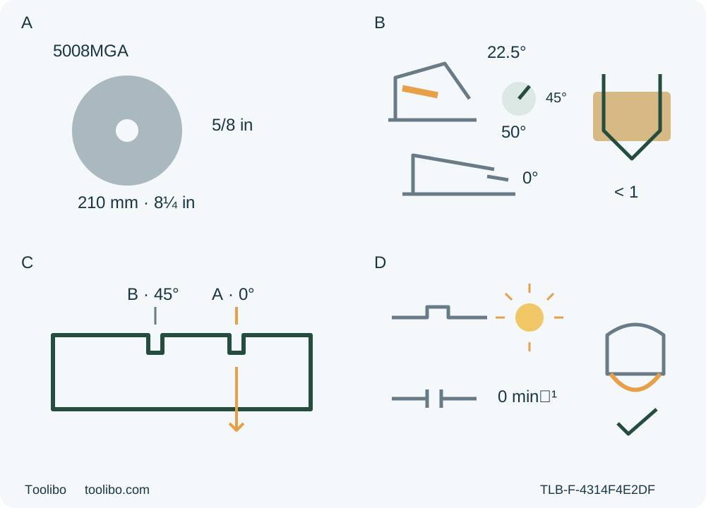
A identifies the original 210 mm/8¼-inch, 5/8-inch assembly. B separates the rear depth lever, angle-range stopper and front locking lever with partial-tooth depth. C shows right A for square cuts and left B for 45 degrees. D distinguishes plugged lamp from physical disconnection and actual stopped, guarded condition.
A · Identify the original system
Actual 5008MGA/884738A940 and approved original 210 mm/8¼-inch, 5/8-inch wood assembly must match, with actual rating and hardware qualification; no fitting or kit inference.
B · Separate range from locking
Unplugged depth adjustment must leave less than a full tooth while cutting through. The 22.5°/45°/50° stopper selects range; the separate front lever must lock actual zero.
C · Verify the right A line
Right A belongs to the square cut; left B/45° does not. Check the actual blade line on equally safe scrap and preserve retained-base support.
D · Do not confuse light and isolation
The lamp lights whenever plugged; neither lamp state nor a presumed brake time proves safety. Require actual stop and guard coverage before setdown, then unplug for acceptance.
Original concepts are isolated recognition aids, not scale drawings or fitting, energized diagnostic or high-angle instructions. A does not derive a numerical blade-rating rule from motor speed. B requires actual through-cut and less than a full tooth; the angle stopper is not a lock. C is an approximate reference, not a factory offset. D describes the lamp state without instructing a live test; actual complete stop and guard coverage still precede safe setdown and unplugging. No brake stopping time is promised.
A discontinued model can still need an exact owner workflow
The current Makita US page identifies the 5008MGA as discontinued and still supplies its manufacturer documentation. That is useful evidence for an existing owner, not a promise of current stock, accessories or a new kit. This workflow is for the actual US 5008MGA matched to the shared 5008MG/5008MGA manual 884738A940, whose back page also identifies 5008MGA-1. It ends with one modest, fully supported square crosscut in known loose wood and an unplugged assessment of the result.
The 210 mm/8¼-inch body is not a 5007MGA with a different carton. Nor does the shared manual give a plain 5008MG the MGA’s electric brake. Confirm the actual model, nameplate, controls and supplied instructions before treating any paragraph below as applicable. An altered, unidentified or poorly documented tool stays on hold for qualified clarification.
Two other prerequisites are already in place: the original manufacturer-approved wood blade and correctly matched mounting assembly, and the complete qualified native dust joint with a suitable Makita extractor. This is an operation-and-acceptance guide, not a blade, ring, adapter or electrical commissioning tutorial.
Establish the original assembly, supply and dust system
The selected manual gives a 210 mm/8¼-inch blade and a 5200 rpm no-load motor speed. The dated US leaflet identifies a 5/8-inch arbor and an original framing-blade listing. Its historical included-equipment list is not proof that your used saw contains that blade or that the same package is currently sold. The actual installed blade must already be identified, manufacturer-approved for this exact assembly and wood, correctly rated and in sound condition, with the correct original flanges, ring and bolt. Unknown rating, mounting identity or approval means hold. Do not turn the motor’s 5200 rpm figure into a claimed numerical blade-rating instruction that this manual does not state.
Inspect the accessible blade and hardware while unplugged. Dullness, damage, incorrect or loose washers or bolt, rubbing, binding, a distorted base, damaged handle or unexplained vibration requires qualified correction before use. Do not remove the blade to investigate within this workflow, convert the ring, guess a tightening torque or make a powered fault test. The fact that a blade fits through a guard does not establish compatibility.
The US leaflet specifies 120 V and 15 A; match the actual nameplate, sound cord and plug to the actual appropriate supply. Do not modify a plug or adapt an unsuitable circuit. The manual requires a matching outlet, protection from rain and wet conditions, and a suitable outdoor extension when used outdoors. It does not provide a model-specific extension-size table here, so do not borrow one from another saw. Arrange a competent supply solution if the actual cord route or extension suitability is uncertain.
For this sample, require the already correctly installed optional native dust joint, secured with its intended screws, and the actual documented hose connection to a suitable Makita vacuum. The manual shows this arrangement but supplies no universal hose diameter or cross-model adapter permission. Verify the complete existing arrangement and the extractor’s own material, operating and maintenance instructions. Missing instructions, an uncertain joint or a hose that interferes with the lower guard means hold, not a partial retrofit.
Make and inspect hose connections with the saw OFF, fully stopped and unplugged, and the extractor isolated as its instructions require. Route hose and power cord clear of the cutting path, waste, clamps and operator travel, without pulling on the tool. Activate and verify the qualified extractor before cutting. The leaflet’s dust blower helps the sightline; it is not a substitute for extraction, ventilation or the manual’s dust mask.
Prepare the place and the isolated tool
Use a dry, well-lit workplace with secure footing, no flammable or explosive atmosphere and no bystanders in the work zone. Choose known dry wood appropriate to the original approved blade, not an unidentified coating or salvage panel. Inspect the whole proposed route and remaining stock for nails and other foreign material. The manual’s cautions concerning damp, treated and knotted timber do not broaden this modest clean-wood sample into those tasks.
Wear eye protection, a dust mask and hearing protection as the manual requires, with suitable ventilation and material-specific exposure controls. Keep clothing, hair and jewelry away from moving parts. Neither a brake nor a small sample reduces these obligations.
Unplug before adjustment and inspection. Check that the trigger moves correctly and returns to OFF when released, and remove setup keys before reconnecting. Examine the cord, housing, grips and accessible fasteners. A switch or cord problem stays out of service; a glowing lamp does not make it safe.
Check lower-guard freedom, instantaneous closure and spring operation before use. Verify clearance from the blade and other parts throughout all angles and depths of cut, including that the retracting handle does not touch the housing. After a drop, reassess for a bent or damaged guard. A slow return, obstruction or faulty spring requires service before use; never tie or clamp the guard open. The ordinary edge-entry cut below uses its automatic action, not manual hold-open control. This guide excludes plunge and compound-cut exceptions.
Separate depth, angle range and the angle lock
At the rear depth guide, release the lever, move the base up or down as the actual mechanism requires, then secure it. Select a through-cut depth that leaves less than a full tooth visible beneath the actual stock, while clearing every support and clamp. This follows the stricter general safety wording even though the later depth paragraph says no more than one tooth. Do not copy a scale value from another piece or use maximum depth simply because it is available.
At the front, the positive stopper and the bevel locking lever do different jobs. The stopper’s 22.5°, 45° and 50° positions select an available angle range; they do not lock the base. Each documented range includes zero. For this square-only sample, establish actual zero and tighten the bevel lever securely under the matched instructions. Do not turn the stopper into a fourth lock, force it past its mechanism or begin an angled cut from this article. If the actual base cannot be securely set and verified square, seek qualified correction rather than adjusting the factory alignment screw here.
The sightline labeled A, on the right, is the straight-cut reference; B on the left is for 45 degrees and is not used. The reference is not a guaranteed kerf offset. Verify the real blade line on equally safe scrap before a dimension-critical piece, and keep the kerf on the intended waste side. Measure the actual depth and reference again after any relevant change; a previous sample is not permanent calibration.
Plan both pieces and the entire travel
Mark a square line from a reliable straight reference edge and identify the wanted piece. Choose an end cut that is modest enough to complete without changing grips, reaching over the blade or shifting a clamp during operation. Use a stable work platform, not a piece balanced on a knee or held in a hand.
Clamp the retained work securely. Keep the wider portion of the saw base on the solidly supported retained piece, not on the part that will fall away. Independently support the waste through separation so it cannot sag, twist or close the kerf, while leaving it free to separate rather than clamping the blade into the cut. Support large stock on both sides near the line and near its edges, keeping the blade path clear. Neither hand catches an offcut. If the real piece is too small to clamp, the base loses support or a safe exit cannot be established, use a qualified alternative or hold the task; no universal overhang or load rating is invented here.
With the tool unplugged and blade guarded, check reach and cord/hose clearance beside or safely above the planned path, without tooth contact or forcing the guard. Confirm continuous base support and a clear exit. Do not call this an unpowered cut or push an exposed stationary blade into the wood. If the setup cannot be assessed safely while isolated, it is not ready for power.
Understand the lamp before connecting
The lamp comes on whenever this tool is plugged in, and remains on until it is unplugged. It is not a separate lamp-switch system or a trigger-only preview mode. Check OFF before connecting; never interpret light as proof that the trigger, brake or motor is sound. Do not look directly into the lamp or strike it.
The manual discusses several possible causes when light or motor behavior is abnormal. Those are not permission for electrical diagnosis here. Unexpected behavior means stop, unplug and obtain qualified assessment, not repeated trigger pulls or a guessed brush replacement. A dark lamp is not evidence of disconnection: inspect the actual unplugged cord end.
Complete the normal cut and verify the stop
Once all prerequisites are met, connect to the qualified supply and ensure the extractor is operating. Hold the rear handle and front grip firmly, using the insulated gripping surfaces; position the body to either side rather than in the blade line. Keep hands out of the cutting area, away from the underside and never behind the saw. Do not leave a grip to move a hose or steady waste.
Set the base on supported work with the blade clear. Pull and hold the trigger, allow full speed, then feed forward gently in a straight line, keeping the base flat and the advance uniform. Do not force the motor or twist the saw back toward a missed line. Loss of support, unusual noise, vibration, resistance or dust-control failure means stop rather than press on.
For binding or any interruption, release the trigger and hold the tool motionless until the blade completely stops. Never pull back or lift a moving blade from a trapped kerf. Unplug before investigation; an unstable trapped-tool situation needs qualified help. Restarting an old kerf is outside this workflow.
After a normally completed cut, release the trigger and wait for actual complete standstill. The MGA-only electric brake is not a lower guard and has no guaranteed stopping time in this guide. Consistent failure to stop quickly after release requires Makita service; do not deliberately create or repeatedly reproduce a fault. Confirm guard coverage and full stop before safely setting down, then unplug before touching the pieces or checking the tool.
Accept a measured result, not just a separated board
Measure the wanted length from its established datum and check squareness, straightness, both faces and the cut edge. Look for splitting, burning, severe breakout, a wandering kerf or evidence that either portion lost support. Accept only the result needed for the actual task; no invented machining tolerance, shelf load or structural claim follows from this sample.
An unsatisfactory result calls for isolated assessment of material, marking, support and tool condition, followed by qualified correction where needed—not forced steering or a second live fault test. Record the model/manual match, original assembly identity, actual supply and extraction, depth, support plan and measured result.
Store the unplugged tool dry and protected. The lamp lens may be wiped carefully with a dry cloth without scratching it. Blade cleaning/removal, ring fitting, brush replacement, alignment adjustment and the manual’s post-brush no-load break-in and brake check remain qualified maintenance, not part of this owner sample. Keeping those boundaries clear lets an existing discontinued tool have a documented task without turning old manufacturer service instructions into an improvised repair course.
Models referenced