
Retained support, cable routing and two stopping conditions
A shows an isolated upward-travel rehearsal with the blade on the right and broad retained base left; B routes the cord from the rear away from the cut; C checks complete stop before isolated inspection; D shows stopped and guarded setdown.
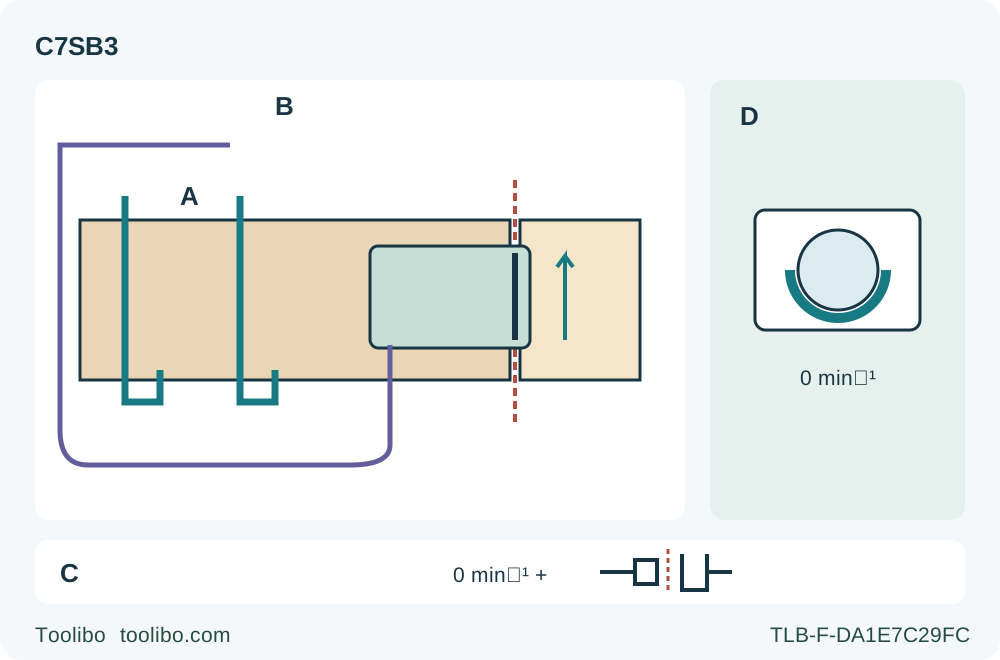
A · Keep retained-side support
While unplugged, rehearse the complete path with the wider base supported on retained wood and all clamps and supports clear of the blade.
B · Check the whole cord route
Use the actual holder to direct the cord sideways, then verify the remaining cable follows without catching or crossing the blade path; both hands remain available for gripping.
C · Stop, then isolate
If binding or abnormal behavior occurs, release the trigger and hold motionless until full stop. Unplug before checking the cause or changing settings.
D · Require both setdown conditions
Do not set down until the blade has completely stopped and the lower guard covers it. The listed absence of an electric brake makes a guessed timer inappropriate.
The plan is an unplugged rehearsal, not a live-cut hand-position diagram. Upward travel with the cut on the right matches the source operating perspective; the retained portion supports the broad base on the left. B is a conceptual whole-cord route, not an exact holder threading drawing or a guarantee against snags. C requires complete stop and physical unplugging before inspection. D requires both standstill and closed lower guard before setdown; no fixed brake interval is claimed.
The C7SB3’s cord holder and large adjustment levers are useful only when they are part of a complete setup. The holder can direct the cable sideways, but cannot keep a slack loop out of the cut by itself. The depth and bevel controls share the name lever (A) in the manual, but lock different adjustments. The spindle lock is a third, unrelated control. This owner workflow separates them before making a supported square wood sample.
It uses the exact US C7SB3 documentation currently linked by Metabo HPT: the Hitachi-branded C99722362 F manual with a September 2017 layout date. A current link does not turn that document into a newly issued manual. Match the actual tool, controls and nameplate to it. Keep the correctly installed original blade and mounting assembly. This is not a replacement-blade, pocket-cut, high-angle, calibration or internal-repair tutorial.
Qualify the documented assembly, not a carton description
The manual specifies a 7-1/4 in (184 mm) blade with a 5/8 in (15.9 mm) hole. The tool’s documented no-load speed is 6000 rpm. Its original wood-cutting blade must be the correct specified assembly, suitable for the tool’s speed, with sound matching washers and a securely fitted flange bolt. Inspect while switched off and unplugged. If installation, rotation, flange identity or condition is uncertain, stop and resolve the complete assembly through the exact instructions or qualified service instead of improvising a torque value.
There is a real accessory-identity boundary: the dated manual lists standard blade 115429, whereas the current product lists included blade 372102. These numbers are not evidence that the blades are interchangeable or that an owner’s carton contained either particular item. This guide relies on an already correctly qualified original assembly, not a new replacement recommendation. A common model name is insufficient to settle a changed accessory.
The source table includes more than one electrical supply description. This workflow is limited to actual nameplate-matched 120 V AC, 60 Hz operation, not a general DC-use instruction. Inspect the cord, plug and outlet fit. A loose receptacle needs appropriate repair by a licensed electrician; do not hold the plug in place or tolerate heating. Use a suitable direct outlet for this sample, avoiding an improvised extension arrangement. Double insulation does not permit wet operation or damaged electrical parts.
Identify and check the three separate functions
Keep the switch OFF and remove the plug before touching adjustment controls. Confirm the switch moves normally and returns to OFF. The documented cutting sequence is trigger on and release to stop; do not invent a lock-off button because another circular saw has one. Do not energize a tool with a defective switch.
The depth lever (A) is at the rear depth link. With the base supported, loosen this lever, hold the base with one hand and move the main body up or down to obtain the required depth. Lock it securely and verify actual projection through the intended stock. Less than a full tooth should be visible below the workpiece. Do not rely on the scale alone or set maximum depth simply because the sample is thin.
The front bevel lever (A) locks the inclination scale. Set zero and secure it independently of the depth lever. The manual describes a separate outward movement for the 45–55-degree range; recognition of that control is not a reason to use it in this square-cut task. A loose front lever cannot be compensated for by holding the saw harder.
The spindle lock lever belongs to blade servicing. It is not a depth lock, brake or running control. Leave the original blade assembly in its normal operating condition, with that lock released. This guide does not give a partial blade-removal sequence or ask the owner to press the lock to stop a coasting blade.
Confirm the guard and work area before choosing a guide
Check the lower guard using its retracting handle while unplugged. It must move freely, close instantly and clear the blade and other parts at all angles and depths of cut. Check its spring action and look for damage or accumulated debris. A sticking or bent guard requires correction before use; do not tie it open. For this normal edge-start cut, the guard should operate automatically. The manual’s pocket-cut section is not part of this workflow.
Choose a clean, dry, known piece of wood suitable for the installed blade, with enough retained area for the wider portion of the saw base. Inspect for and remove nails; reject uncertain inclusions and hazardous finishes. Do not substitute a log, tree branch, metal or abrasive cutting wheel. Avoid loose clothing and gloves liable to wind into moving parts. Wear ANSI Z87.1 eye protection with side shields, hearing protection and appropriate dust protection, with ventilation.
The built-in blower improves visibility of the line; it does not collect the dust. Do not interpret a clearer line as evidence that inhalation exposure has disappeared or invent an extraction nozzle not established by these instructions. If the material requires controls that this work arrangement cannot provide, choose a suitable alternative rather than proceeding because the motor has sufficient power.
Keep the retained base supported through the exit
Mark the intended finished edge and identify the waste side. Clamp the retained piece to a stable work surface. Plan support on both sides near the cut and near panel edges so sagging cannot close the kerf. All supports must clear the blade below the stock. Keep the wider part of the base on the solidly supported retained portion, not on the piece that will fall away. The offcut must not be trapped against the blade.
Use a rip fence or straightedge guide for ripping. If using the original optional fence system, identify the guide 302691, wing bolt 302697 and lock spring 947859 as a complete matched set. With the tool unplugged, install wing bolt (B) and the lock spring on the base, insert the guide from the chosen side, set its intended position and tighten the wing bolt; the edge-following guide must remain clear of the blade and free guard movement. Do not replace a missing spring or fastener with an arbitrary shop part.
Alternatively, secure a suitable straightedge and establish its actual offset on matching scrap. No factory offset is assumed here. In either arrangement, choose a useful sample length that allows stable starting and finishing positions without reaching across the blade. Check that all clamps and guide components clear the base and housing for the whole travel. A guide controls direction, not the support or exposure beneath the work.
Route the cord as a moving part of the setup
While still unplugged, pass the cord through its holder as shown in the manual so it can be drawn sideways. The holder does not secure the entire cable or authorize a tight bend. Arrange the remaining length away from the blade, the offcut and possible snag points. It must follow without pulling the saw sideways or lifting the base as the cut advances.
Rehearse the path without power and with the blade guarded. Check the start, middle and exit, not only the first few centimetres. Confirm that the cord cannot hook a clamp, wrap around the work edge or be dragged into the opening after the offcut separates. If the route only works while a hand holds the cable, revise it: both hands belong on the saw during cutting.
At the front base notch, identify the uninclined reference rather than the separate 45-degree reference. Compare the intended line with the actual original blade’s kerf on a supported sample. The notch is a locating aid, not a substitute for checking the retained dimension. Record which guide and contact side are used so a later setup does not silently inherit an unrelated offset.
Complete an ordinary forward sample
Before plugging in, check that both adjustment levers are locked, the spindle lock is released, the guard returns correctly and no wrench remains on the tool. Verify the support, clamp clearances and cable route once more. Keep balanced footing and the body out of line with the blade. Hold the main and forward grip positions firmly with both hands.
At the supported start, keep the blade clear of the wood. Pull the trigger before contact and wait for full speed. Advance straight at a steady, controlled rate with the base flat; do not force the motor down or twist the tool to chase a mark. Keep hands away from the blade and guard travel. Neither hand steadies the stock or reaches under it.
Continue through the planned exit without losing retained-side support. Release the trigger at normal completion and maintain control until the blade completely stops. Confirm that the lower guard covers the blade before setting the tool down. The current product expressly lists no electric brake; there is no fixed stopping time to count instead of observing standstill. Never use the spindle lock or side pressure on the blade as a stopping device.
If the blade binds, stops unexpectedly or makes abnormal noise, switch off immediately and hold the saw motionless until complete stop. Do not withdraw a rotating blade or pull backward through the cut. Unplug before inspection. Resolve the cause before further work; unexplained noise, movement, switch failure or guard malfunction requires qualified attention, not another trial. This guide does not provide a restart-in-the-kerf recipe.
Accept the result and leave the tool ready for safe storage
With the blade stopped and plug removed, measure the sample at more than one location. Check retained width, edge straightness, squareness and finish. Confirm that the guide and clamps did not move, the locks held and the cord followed without snagging. A dimensionally acceptable piece is not a pass if support or guard behavior was unreliable.
Repeat on suitable scrap if the reference needs confirmation. If the cut is wrong, separate setup causes before changing anything: misplaced guide, wrong notch reference, inadequate support, excessive depth, a blade needing attention or loss of square. Do not alter the base calibration screw as an improvised way to compensate for a moving guide. Obtain the correct repair where required.
Keep the tool disconnected for cleaning and inspection. The manual allows dry-air cleaning of guard and ventilation areas with safety goggles and a dust mask; do not turn that into internal disassembly. Exterior cleaning uses a soft cloth lightly dampened with soapy water, followed by thorough drying, without liquid ingress or damaging solvents. Maintain free guard movement, and refer damaged electrical parts and internal work to appropriate authorized service. Store only after the blade is stopped, guarded and disconnected.
Models referenced