
Keep evidence, paired limits and physical isolation separate
A pairs actual blade and instruction evidence without a replacement-size claim. B separates the approximate 5–10 mm depth condition and a less-than-full-tooth concept with a plus sign. C identifies grip numbers 1 and 4 and the zero-bevel clamp 22 without a running pose. D shows a detached battery and zero rotation beside a connected industrial extractor and mask.
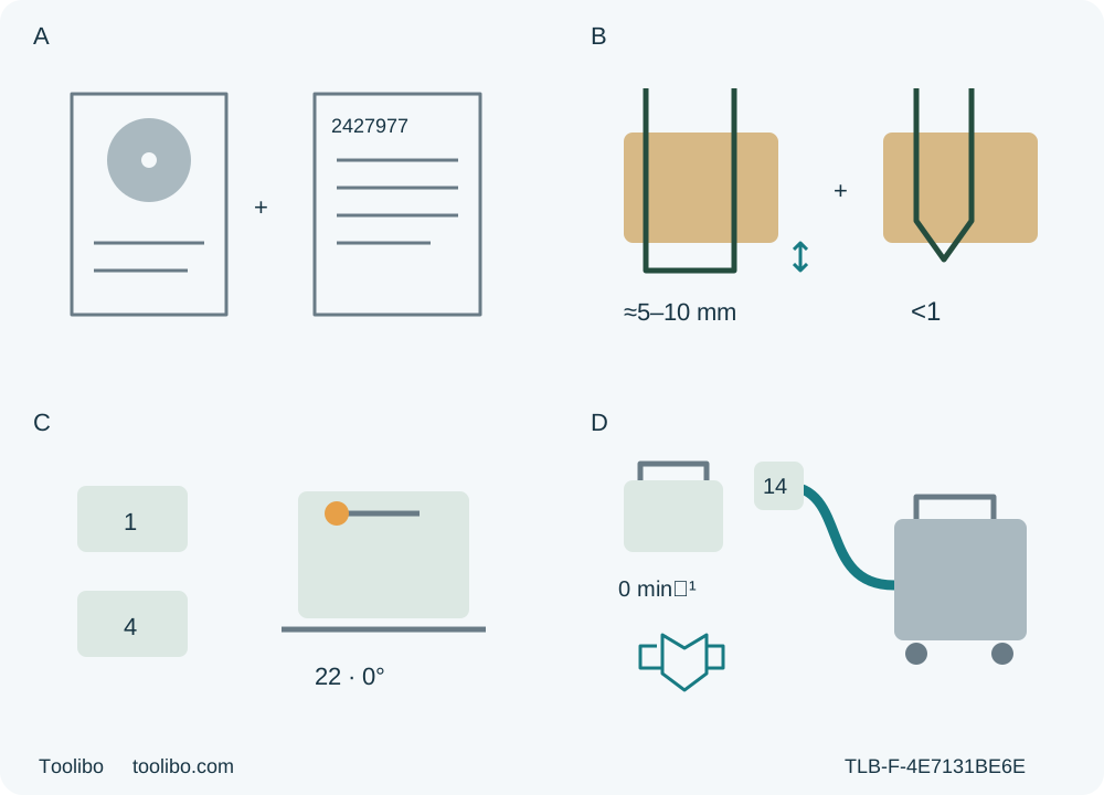
A · Resolve original applicability
Actual small-base generation 02, supplied POS3 and original approved blade dimensions/rating must be qualified together. Unknown or conflicting actual assembly is a pre-cut hold.
B · Establish both depth conditions
Battery out: actual through-cut must satisfy approximately 5–10 mm extra depth and less than a full tooth. Neither statement overrides the other; unresolved geometry goes to Hilti.
C · Identify the actual controls
Battery out: secure square bevel at zero with actual clamp 22. During the qualified ordinary cut, both designated insulated gripping surfaces 1 and 4 remain in use.
D · Separate stop from isolation
On interruption release immediately and hold motionless to full standstill, then isolate safely; no trigger-held pullback. Actual industrial extraction plus task mask/eye/hearing protection remains required.
Conceptual isolated symbols are not to scale. A does not resolve the 190 mm/7-1/4 in source discrepancy. B requires both actual depth conditions; it does not assert that every original blade can satisfy them. If not, hold before cutting. C identifies common controls only, not large-base rail features or a hand/body plan. D combines separate isolation and dust prerequisites; it is not an AutoStart or battery diagnostic procedure. Actual standstill, not a two-second timer, governs handling.
This is a conditional existing-owner workflow for the US Hilti SC 30WR-22 generation 02, selected item 2422186 with the small base, matched to operating instructions 2427977, Pos. 3, dated 20250207. Hilti limits operation, servicing and maintenance to trained, authorized professional personnel informed about the hazards. Reading this article does not supply that training or authorize an unfamiliar operator.
The finished task is one ordinary square, edge-entry crosscut in known loose solid wood, followed by an isolated acceptance check. Before reaching that cut, the owner must positively resolve the actual original blade, body, document, power, extraction and depth requirements below. An unresolved requirement means hold before cutting, not “try a shallow sample and see.”
1. Resolve the actual original system—not the conflicting headlines
The current US product description combines 190 mm with 7-1/4 in; those dimensions are not equivalent. The linked manual specifies 7-1/4 in, a 5/8 in arbor, 0.7–1.8 mm blade-disc thickness, 2.5 mm kerf and a no-load speed of 6250 rpm. The product and photograph also present 70 mm depth, while the manual gives 67 mm; the product’s 50-degree claim and manual’s 53-degree range differ. This guide does not silently convert, select a replacement blade or synthesize a new capacity limit from those statements.
Only proceed when the actual original Hilti-recommended wood blade, its permitted dimensions and speed, the physical saw/nameplate and the supplied matching instructions have been positively qualified together. Its rated speed must be at least the maximum marked on the actual tool, and the blade’s own maximum must not be exceeded. It must be suitable for the actual wood and comply with EN 847-1. If the diameter or another original-assembly requirement remains inconsistent or unknown, obtain exact Hilti clarification before use. “Factory fitted” is not a reason to disregard a mismatch.
The original blade must be sharp, clean and flawless, with sound teeth and body, correct existing rotation/orientation and original approved washers, flange and bolt. Cracks, deformation, loose or wrong hardware, binding or unexplained previous fitting work are holds. The general blade leaflet also rejects carbide teeth worn below its 1 mm limits; it is not permission to sharpen or repair teeth yourself. No fitting, reducer ring, torque, flange removal or internal cleaning procedure is taught here.
Confirm the actual small-base generation-02 controls and supplied POS3 document. The manual overview expressly illustrates a large-base example. Its two-arm guide installation and direct rail features must not be assumed on the selected US small base. This task uses the actual matching zero-degree line indicator for an ordinary marked-line crosscut; it does not fit a parallel guide or rail adapter. Unknown control or base applicability is another pre-cut hold.
2. Understand the AutoStart hazard before connecting power
A stopped motor does not establish isolation on this saw. The manual describes AutoStart after an unplanned stop while the on/off switch remains held, including a brief automatic-restart window. That convenience description must not be mistaken for a safe-stop timer or a recovery instruction in this workflow.
For any interruption, binding, stall or abnormality, release the on/off switch immediately and hold the saw motionless until the blade has completely stopped. Do not keep the trigger held, pull the saw backwards to provoke a restart, lift a moving blade or recreate the fault. Isolate the battery before investigation when safely possible. The manual’s general kickback stop-and-hold rule governs this conservative route; no AutoStart technique, reset or trapped-tool extraction is included. Two seconds is not a promise that the blade is safely stopped. An unresolved or recurring problem requires Hilti Service.
3. Qualify an already commissioned Nuron system
Use only the actual approved battery and charger combination already commissioned under their complete matching instructions and Hilti battery safety guidance. The exact manual table lists B 22-55 (01), B 22-85 (01), B 22-110 (01), B 22-170 (01) and B 22-255 (01), with C 4-22, C 6-22 and C 8-22 chargers. Record the actual pair and its approval rather than treating the table as a first-time charging lesson. The product photograph’s B 22-175 wording is not evidence that it equals B 22-170. No battery or charger is promised as included.
The pack must already be fully charged before first use under its own instructions, intact and correctly maintained. Do not use or charge a pack that has suffered an impact or other damage, been soaked, modified, repaired or recycled into a replacement pack. Keep it away from rain, liquids, heat, flame and conducting objects; do not touch its poles with fingers or tools. A status light is not proof that impact or misuse damage is absent. This guide does not run the battery health test or teach fault/charging resets.
The manual gives −17°C to 60°C as the tool and battery operating ambient range. Its separate storage limits are −20°C to 70°C for the tool and −20°C to 40°C for the battery; do not use a storage or charging figure as an operating authorization. Actual complete battery instructions remain mandatory. A questionable power system holds the whole task.
4. Isolate, inspect and establish the two depth conditions
Release the on/off switch and confirm the switch-on interlock returns to its locked position. Wait for complete blade standstill, press the battery release and remove the battery fully. Keep it out for inspection, settings, connection work and measurement. The interlock alone is not physical isolation.
Inspect the housing, base, grips, switches, clamps, original accessible mounting hardware and blade condition. A damaged tool or a switch that does not reliably control it must not be tested under power. Before each use, raise the lower guard with its operating lever and confirm free movement, immediate closing and clearance from the blade and other parts at all angles and depths of cut. Check the spring, including after any drop. After cleaning or maintenance, the guard must again close quickly and completely and all safety devices must be correctly fitted. Guard malfunction requires Hilti Service; never tie or clamp it open.
With the battery removed, release the actual rear depth-clamping lever, move the body in the documented scissoring movement to set depth, then secure the lever. Two source requirements must both be satisfied: the depth section calls for approximately 5–10 mm more than the material thickness, while the safety section requires less than a full tooth visible below the work. Do not assume these agree on the actual blade and stock. Verify the actual isolated geometry without touching teeth; if both cannot be established, hold for Hilti clarification. The numeric sentence never overrides the tooth limit.
Release the actual bevel-adjustment clamp, set zero and lock it securely. No maximum-angle experiment or preselector tutorial is included. Confirm the actual zero-degree cutting mark on this base; do not copy a left/right notch layout from another variant. If settings shift, cannot lock or cannot be identified confidently, do not proceed. Remove all adjusting tools before reconnection, keeping the supplied key securely in its designated storage rather than loose near moving parts.
5. Establish active industrial extraction and the complete work path
This selected route retains the strongest combined dust precautions in the manual: a task-appropriate dust mask, eye and hearing protection, good ventilation and an industrial vacuum with an officially approved protection class suited to the actual dust and local requirements. The later permissive no-extraction passage does not waive those prerequisites here. Neither a marketing capture percentage nor a vacuum’s headline specification qualifies the actual installation.
With the saw isolated and the extractor isolated under its own instructions, connect the actual qualified hose/adapter arrangement to native connector 14 according to the matching tool-side and extractor instructions. The statement about common hoses does not guarantee a particular fit or approve an unknown adapter. If those actual instructions or suitable performance cannot be established, hold before cutting. No Bosch pressure/flow numbers are transferred. Activate and check the prepared extractor before the cut; an attached but inactive hose is insufficient.
Choose clean, dry, uncoated and untreated loose flat solid wood, large enough to accommodate the whole base in the cut and approved for the retained blade. Inspect the entire route and remaining stock for nails, screws, stones and other foreign objects. Exclude installed work, concealed services, unknown coatings, drywall, metal and extremely small pieces. Keep the tool and workplace dry, well lit and free from flammable liquids, gases, explosive dust conditions and bystanders. Do not work overhead or beyond a stable comfortable reach.
Mark a square line from a verified reference edge and identify retained wood and waste. Clamp the retained work to a stable platform. Support both portions independently, near the cut and edges where needed to prevent sagging, while keeping supports out of the blade path. The waste must separate freely without closing the kerf; neither your hand nor a helper substitutes for the fixture. Do not clamp the two portions across the cut.
Check the full base, clamp, hose, handle and exit paths while isolated, beside or safely above the route with the blade covered and no tooth contact. The hose must not snag or pull the saw, and both designated grips must remain available. Plan an ordinary clear entry and complete edge-to-edge exit, not an internal opening or a partial-line escape. If actual workholding or reach cannot close, obtain a qualified setup rather than invent an unsupported overhang or small-piece recut.
6. Start with a clear blade and finish under control
Only after all gates pass, confirm OFF and the active interlock, clean foreign matter from the permitted product contact area, then push the already qualified battery in until it clicks audibly. Check that it is securely seated. If the release button is pressed to read status, check secure engagement again; do not leave the pack partly released. Do not look into the incorporated LED or direct it at another person’s face.
Hold the two designated gripping surfaces identified as 1 and 4 in the matched overview, using their insulated surfaces. Keep hands away from the cutting area, underside, rotating parts and chip channel. Position your body beside the blade line and maintain stable footing. Bring the front edge of the base onto the supported retained stock with the blade clear, and align the actual zero-degree line indicator with the mark.
Press and hold the switch-on interlock, then press and hold the on/off switch. The interlock may be released once the on/off switch is held. Let the saw run clear before bringing the blade into contact; do not start against the wood. Guide it along the line at a suitable controlled feed for a smooth cut, with stable base support and both hands maintained. The lower guard operates automatically for this ordinary edge-entry cut; do not manually hold it open. Avoid forcing, twisting, sideways braking pressure or overheating the teeth.
On normal complete separation, release the on/off switch and wait for actual full standstill while maintaining control. Confirm the lower guard covers the blade before setting down, then remove the battery before measuring, moving supports or handling the sample. No elapsed-time brake guarantee replaces observation of standstill. If anything interrupts the cut, immediately use the release-and-motionless-hold rule above, not AutoStart or a pullback.
7. Accept the result and preserve the evidence
With the battery out and all movement stopped, inspect the finished piece and remaining work. Confirm full separation, intended size, straight line and square cut geometry using appropriate measuring tools. Inspect both faces and the edge for unacceptable tear-out, burning, rubbing or damaged teeth. Check whether clamps/supports moved, extraction failed or the tool behaved abnormally. Beware of sharp splinters when handling the edges; do not sweep bare fingers along them. The required tolerance is the actual project’s acceptance criterion, not a universal manufacturer promise.
If the sample fails, record whether the issue is geometry, support, original assembly, dust control or unexplained tool behavior. Correct only safely isolated, documented setup issues within competence; an unknown blade fit, guard failure or repeated abnormal stop goes to Hilti Service. Do not use another powered cut to demonstrate a suspected fault.
For bounded exterior care, keep the battery removed and allow hot parts to cool. Use a dry soft brush for accessible ventilation openings and a slightly damp cloth on the housing; do not use silicone-containing cleaners. Product contacts may be cleaned with a dry clean cloth, but do not touch battery contacts or remove their factory grease. The manual’s internal guard and chip-channel cleaning requires blade removal; that is outside this original-assembly workflow. Blockage or poor guard return therefore requires qualified service rather than partial disassembly.
Store and transport with batteries removed, protected against contact and impact, under the full instructions. Keep the exact generation/base/manual match, original blade approval, paired depth evidence, actual power and industrial extraction records and sample result. A clear hold with the unresolved requirement identified is preferable to an apparently complete cut based on a guessed conversion or restart assumption.
Models referenced