
FX2141 isolated control checkpoints
Four panels show a detached battery, depth-bracket notch against upper-guard marks, a separate preset knob and zero-angle locking lever, and a screw-secured 32 mm extraction connection.
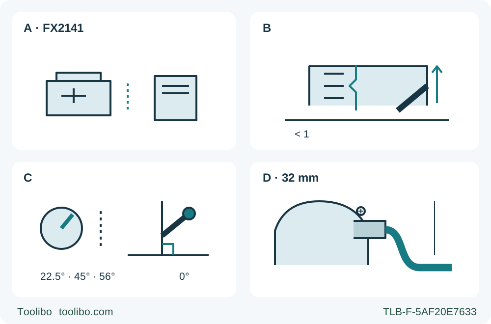
A · Physical isolation
Release the trigger, wait for complete standstill and remove the battery before checks or settings; a dark work light is not isolation.
B · Actual depth
Lift the depth lever toward the motor to loosen, align the bracket notch with upper-guard marks, lock and verify less than a full tooth below the actual work.
C · Two different controls
The preset knob limits travel at documented angles; the separate lever locks the actual zero-bevel setting. No high-angle or calibration procedure is depicted.
D · Existing extraction
With the battery removed, verify the correct complete adapter, provided screw and suitable 32 mm hose. Confirm airflow and full-route hose freedom; wear the required dust mask.
All panels concern an isolated tool with its battery removed. B is a conceptual notch-to-mark relationship, not a scale or factory depth guarantee. C distinguishes a travel stop from the separate angle lock; the sample remains at zero bevel. D requires an already qualified complete extraction assembly, not a guard-lever retrofit.
This workflow is for an existing US FLEX FX2141, not the FX2141R rear-handle saw. Its outcome is an accepted square wood sample with the original qualified assembly, secure depth and bevel settings, a functioning dust route and a support plan that lasts through separation. Match the actual tool and supplied instructions to the January 2021 FX2141 manual linked by the current manufacturer product page.
The bevel stop is only one part of the owner system. A preset knob limits bevel travel; a different lever locks the actual angle. Knowing that distinction does not by itself qualify the battery, blade, guard or workpiece. This task stays at zero bevel and does not teach high-angle cutting or calibration.
Establish the actual owner system
Require the already correctly installed, approved original wood blade and matching mounting parts. The manual specifies 7-1/4 in / 184 mm and a 5/8 in / 16 mm arbor, with a blade rated 5800 rpm or greater. A blade must not be so thick that the outer washer cannot engage the spindle’s flat. These are qualification conditions, not permission to select or fit a replacement. Dullness, damage, uncertain mounting or unknown service history means hold for the complete exact instructions and qualified correction.
Use an already commissioned genuine power system within the manual’s actual list: FX0111 2.5 Ah, FX0121 5 Ah, FX0221 8 Ah or FX0231 12 Ah battery, with the applicable FX0411 or FX0421 charger and its complete supplied instructions. Verify the actual labels and established pairing rather than relying on pack appearance. Charging, damaged-pack assessment and a new pairing are outside this guide.
The current product page also lists later stacked-lithium kits and broad system compatibility. That later marketing does not rewrite the 2021 manual’s exclusive list for this bounded workflow. Nor does this limitation establish that later packs are unsafe. If the actual combination falls outside the documented owner scope, obtain the complete applicable manufacturer instructions before proceeding; do not borrow a kit promise from another configuration.
Release the trigger, wait for complete blade standstill and remove the battery completely before inspection, adjustment or carrying. Use the battery-release button and withdraw the pack; a dark work light is not disconnection. Keep the detached pack protected according to its own instructions, away from loose conductive objects.
Inspect the guard, stock and extraction before setting a cut
With the battery removed, check the lower guard for free movement and immediate closure. Check operation through all angles and depths of cut, and check the spring and retracting lever for proper condition. Do not tie the guard open or make a powered test to demonstrate that a sluggish guard will recover. Damage, interference, missing parts or uncertain closure is a hold for qualified correction.
Choose known, dry, untreated, nail-free loose wood within the blade’s actual approval and the tool’s capacity. Inspect the proposed route for fasteners and foreign material. This is wood cutting only: no metal, masonry, abrasive wheel, concealed installed work or internal plunge. Select manageable stock that allows a continuous feed without reaching across the blade line or changing supports mid-cut. The supplied blade is documented for crosscuts and rips, but that does not qualify an unidentified blade already on a used tool.
Require the existing complete, correctly fitted extraction arrangement. The manual locates the adapter at the upper-guard opening, secured with the provided screw, and specifies a suitable vacuum with a 1-1/4 in / 32 mm hose. Verify that assembly with the battery removed. The product’s accessory list also mentions a lower-guard lever; this guide does not invent a replacement-lever procedure from that list. An incomplete or uncertain retrofit must be resolved under the actual complete supplied instructions before use.
Check unobstructed airflow, secure connection and enough hose length and freedom for the entire route. Hose routing must not catch the guard, guide or clamps or pull the saw sideways. Do not release a grip to manage a snag during the cut. Wear eye protection with side shields marked to comply with ANSI Z87.1, and a full face shield when needed, as specified on printed page 2. Also use appropriate hearing protection and the dust mask the manual requires during use; extraction is not a reason to omit it. Keep bystanders away and arrange ventilation and collection for the actual wood dust.
Set depth from the notch, not from a remembered lever direction
Keep the battery removed. Push the depth-adjustment lever upward toward the motor housing to loosen it. Hold the foot down and use the handle to raise or lower the saw. Align the notch on the depth bracket with the intended depth mark on the upper guard, then tighten the lever and check that the setting is secure.
Confirm the actual tooth projection beneath the stock. The general safety rule requires less than a full tooth visible, while the adjustment page says no more than one tooth and describes common factory marks allowing one tooth. Use the stricter actual less-than-one-tooth setup here; do not assume a convenient preset mark automatically satisfies it for the particular blade and board. Maintain clear space below the entire projected blade path, not just under the entry point.
For zero bevel, loosen the separate bevel-adjustment lever, set the indicator to zero on the quadrant and tighten the lever. The push-turn-release preset knob selects a travel stop at 22.5°, 45° or 56°; it is not the angle lock. This sample does not tilt to those settings. If the actual zero setting cannot be locked securely or the resulting sample is not square, stop for the complete adjustment instructions or qualified service instead of experimenting with the alignment screw.
Qualify the guide, support and actual cut reference
The foot’s zero and 45° references indicate an approximate cut line. Use the zero reference for this task and verify the actual kerf on supported scrap with the same blade and locked settings. Mark the wanted side and waste side, and determine the actual base-contact offset; another saw’s measurement does not transfer. The manual advises placing the good face down to reduce splintering on that face. Confirm the finish on the actual trial rather than promising a chip-free result.
For a guided rip, the manual documents a straight piece of 1 in / 25 mm lumber secured as a board guide, with the right side of the foot against it. Use clamps for this workflow, located clear of the saw’s full travel. The optional FT211 rip fence is a different accessory and is not commissioned here. If the actual guide height or clamp position conflicts with the tool or hose, change the setup before starting.
Secure the retained work to stable supports. Support both portions independently near the cut and edges, with all supports outside the blade path; the waste must separate without closing or pinching the kerf. Keep the broad base supported by the retained piece. Never hold the board on a leg or catch the waste by hand. Assess entry, middle and exit reach beside or safely above the route with battery removed, guard closed and no tooth contact; do not push projected teeth through uncut stock as a rehearsal.
Complete one controlled sample and accept the whole process
Only after the isolated checks pass, confirm the trigger is released, align the raised rib on the qualified battery with the tool groove and slide it into place until the latch snaps. Check that the battery is secured before proceeding. Hold the main handle and auxiliary handle with both hands, body to either side rather than in line with the blade, facing away from the vacuum adapter. Neither hand may obstruct the lower guard. Place the foot on supported stock with the blade clear.
Press and hold the lock-off with the thumb, then squeeze the trigger. Release the lock-off while continuing to hold the trigger for operation. Reach full speed before entering the wood, and feed forward with light, continuous pressure while keeping the foot flat and the guide contact stable. Do not force or twist the saw to correct a missed line.
If binding or interruption occurs, release the trigger and hold the saw motionless until the blade stops. Do not pull a moving blade backward from the kerf. Remove the battery before investigating; interrupted-cut recovery is outside this sample. At normal completion, release the trigger, wait for complete blade standstill and lower-guard coverage before withdrawing and setting the tool down safely. Keep the tool away from clothing and your leg during coastdown. Remove the battery before measuring.
Accept the sample only if the intended dimension, straight edge, square cut and face finish are satisfactory and the process remained controlled: locks secure, guide stationary, base supported, hose clear and waste freely separated. A correct dimension does not excuse guard interference or a shutdown. Record the actual assembly, depth, zero reference and guide relationship before repeating work.
Recognize signals without treating them as restart permission
The work light can illuminate with a slight trigger squeeze before the motor starts and remain on for about ten seconds after release. Neither state proves isolation. The manual describes shutdown when the tool or pack is overloaded or too hot, rapid flashing specifically for overload, and slower flashing for low charge. Do not label every hot shutdown an overload diagnosis. An absent light at start or sudden loss during operation calls for customer service or an authorized service center under the manual.
These signals are reasons to stop and consult the complete instructions, not to perform a live fault test or repeated restart. Charging and recovery procedures are not supplied here. For care, keep the battery removed, avoid liquid entry and refer repair or uncertain cleaning to the exact instructions and qualified service. Store the tool securely indoors, away from children and corrosive substances. The accepted sample establishes one original-assembly wood setup, not permission for new packs, blade fitting, guard retrofits or high-angle work.
Models referenced