
Isolated controls and a complete extraction prerequisite
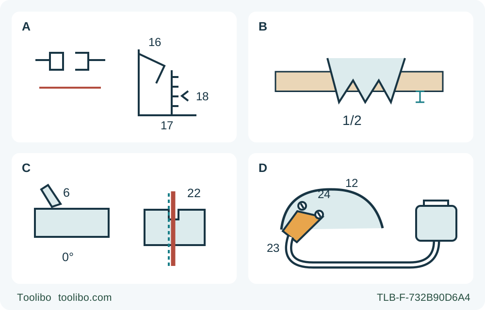
A shows a disconnected cord and depth lever 16 with strap 17 and notch 18; B illustrates half-tooth projection; C distinguishes zero-bevel lever 6 and kerf reference 22; D shows the complete two-screw extraction port and hose.
A · Isolate and identify the depth references
Release the trigger, wait for full standstill and unplug. Raise depth lever 16, set strap 17 against notch 18, then lower the lever securely.
B · Verify actual half-tooth projection
Check the intended material thickness with the saw unplugged; about half a tooth projects below it. Keep the entire tooth path clear of supports.
C · Establish square and kerf placement
With power disconnected, secure zero using lever 6. Confirm indicator 22 against the actual sample: kerf to the right, in waste. No calibration or replacement-blade inference.
D · Require complete suitable extraction
The original qualified port 23 uses two intended screws 24 at upper guard 12. Connect the material-suitable extraction system and clear its hose path before any wood cutting.
This is a controls-only conceptual diagram, not a copy of the contradictory Figure O or a running-cut support plan. A means physical unplugging after full standstill, not a battery instruction. B represents the model-specific half-tooth setting, not a universal millimetre depth. C keeps the zero control separate from the kerf reference; the actual kerf falls to the right of the indicated left blade edge. D is qualification of an already correctly installed port with both intended screws and a suitable connected extractor, not authorization to improvise hardware or infer vacuum adequacy from hose fit.
This is an existing-owner workflow for a Canadian DEWALT DWE575 Type 10 matching the N786997 instructions dated October 2019. It prepares a known, dry, untreated loose-wood sample for a normal square cut, then checks the dimension, squareness and cutting process. The current Canadian product page links this exact Type 10 document. That establishes a Canadian document chain, not equivalence to a US variant, a different type or every newly supplied manual.
Use the complete supplied instructions alongside this guide. The manual is shared with other models and contains several inconsistencies that must not become operating advice. This scope retains an already correctly assembled original wood blade, excludes the disputed support Figure O, and uses the explicit corded isolation and extraction instructions. It does not teach blade replacement, calibration, pocket cutting, stall recovery or brush service. Inexperienced operators require competent supervision under the professional-tool instructions.
Match the actual saw and stop at assembly uncertainty
Confirm DWE575 and Type 10 on the actual identity information, the matching controls and the complete N786997 document. Do not transfer the DWE575SB electric-brake description to this DWE575. A two-second stopping claim from the SB section is not an acceptance criterion for this tool; actual full standstill is required before handling or setting it down.
The document cover calls the saw 7-1/4 in (184 mm), while a replacement paragraph pairs 7-1/4 in with 178 mm. This guide does not silently correct that discrepancy or select a replacement diameter from it. Retain only the original, correctly installed, manufacturer-qualified wood-cutting assembly whose identity, condition, mounting parts and suitability for the actual work are established. If those facts are uncertain, obtain the complete model-specific clarification or qualified correction before proceeding.
Check for visible damage, unsuitable or dull teeth, missing parts or evidence of an improvised washer arrangement without disassembling the blade. The manual requires a blade’s permitted speed to meet or exceed the saw’s speed and correct mounting-hole size and shape. A plausible appearance alone cannot establish those requirements. Do not press the blade lock on a moving saw or use it to stop the blade; this workflow has no reason to operate it.
Choose a manageable piece of known dry untreated wood, free from fasteners and suspect coatings. Reject material that is too short or narrow to clamp and support safely. The manual prohibits metal, plastic, concrete, masonry and fibre cement for this saw. It also identifies damp, green and treated lumber as requiring extra attention; those complications are outside this initial sample, not solved by feeding harder.
Establish corded isolation and a qualified supply
Use the actual nameplate supply requirements, not the current product table’s inconsistent 12 V field. This is a corded tool. The stray battery-removal sentence in the manual’s support section does not describe its isolation method: the assembly, operation and maintenance warnings expressly require switching off and disconnecting from the power source.
Release the trigger and wait for complete blade standstill, then unplug before inspection, adjustment, clearing or accessory work. Keep the plug under your control so nobody can reconnect it unnoticed. Inspect the cord and plug for damage and route them away from heat, sharp edges, the cut and anything that could snag. A damaged cord or a switch that cannot control the tool requires service before use.
If an extension is needed, qualify it from the complete manual table using the actual nameplate current, voltage and total length; this guide does not give a universal gauge or guess the supply from a web field. Do not modify a plug or improvise an electrical repair. Establish a dry, well-lit working location without flammable liquids or gases, with bystanders clear and stable footing throughout the intended travel.
Use the manual’s specified ANSI Z87.1 eye protection (CAN/CSA Z94.3), ANSI S12.6 (S3.19) hearing protection and approved respiratory protection appropriate to the dust. Ordinary spectacles are not safety glasses. Ventilate the area and keep dust away from the face and body. Protection does not make an unknown coating or an unsuitable material acceptable.
Complete extraction is a prerequisite, not an accessory preference
The wood-cutting dust section requires a suitable vacuum extractor designed in compliance with applicable dust-emission requirements, plus approved dust protection. Verify that suitability and compliance from the actual extractor documents; do not infer a numeric threshold or certification from hose fit. The fact that the extraction port may be purchased separately does not turn that requirement into an optional upgrade. Do not start this sample with a missing port or an unqualified collection arrangement.
Require the correct DEWALT-recommended port, already properly installed over the upper guard with both intended screws, and a suitable connected hose and extractor operated under their complete instructions. Figure S identifies port 23, upper guard 12 and screws 24. The present workflow checks that complete existing arrangement; it does not suggest substitute screws, a homemade adapter or an inferred replacement part number.
The manual’s statement that common hoses fit the outlet concerns physical connection, not proof that any household vacuum is adequate for wood dust. Confirm the actual extractor’s suitability and safe collection arrangement. No suction threshold is invented here. With the saw unplugged, arrange the hose and cord so neither can pull the base off line, catch a clamp, obstruct the lower guard or pass through the projected blade path. If that route cannot remain clear through the far end, rearrange or hold the work.
Check the guard, depth and zero setting while unplugged
Before each use, check that the lower guard moves freely and closes immediately. Use its retracting lever as instructed, keeping fingers clear of the teeth, and verify no contact with the blade or another part at all angles and depths of cut. Check the spring’s condition and operation. A missing, damaged, misassembled or sluggish guard must be corrected by appropriate service before use; never tie or clamp it open for the normal cut.
For depth, hold the isolated saw securely and raise lever 16 to loosen. Move the foot plate to the required position, align the relevant mark on depth strap 17 with notch 18 on the upper guard, then lower the lever to retighten. The model-specific guidance calls for about one-half tooth projecting below the actual work, consistent with the general less-than-full-tooth rule. Check the actual projection using the intended material thickness rather than assuming a scale alone settles it. Keep the entire tooth path clear of supports.
Use bevel lever 6 to establish the normal zero-degree setting on the quadrant and retighten firmly. This is an operating setting, not an instruction to adjust calibration screw 19. If the eventual sample is not square despite a secure zero setup, hold further work for the complete documented correction or service rather than turning an unidentified screw until the result looks better.
Make the kerf fall in waste without copying the disputed figure
Kerf indicator 22 corresponds to the left, inner side of the blade, so the actual kerf falls to its right. Mark the wanted line and the waste clearly, and verify the relationship on the sample. If using a clamped straightedge, calibrate the actual blade-to-contact-edge offset rather than adopting a nominal distance from another saw. Keep the same base contact edge throughout the cut.
The manual’s Figure O carries a prohibition symbol while its adjacent prose calls it a correct example. This guide does not reproduce or rely on that figure. The separate, unambiguous instructions require clamped work, support near the cut, both-hand operation and the wider portion of the shoe on the retained, solidly supported piece. Use those requirements to qualify the actual layout, rather than treating a contradictory picture as permission.
Support retained and waste portions independently outside the blade path, with support arranged to avoid sagging and kerf closure. Allow the waste to separate without trapping it or lifting it against the blade. Do not hold short stock by hand, reach below the panel or plan to catch a falling offcut. The manual places the appearance-critical face down; confirm the sample’s face orientation before setting the guide, without compromising support or control.
With the saw unplugged, assess reach and clearances beside or safely above the proposed route, blade guarded and teeth clear of the stock. The tilted body, guide clamps, cord and hose must not interfere even though this is a zero-bevel task. If the planned exit requires overreaching or changing supports mid-cut, the layout is not ready.
Cut once, stop completely and accept the result
Check that the trigger moves properly and returns to OFF before connecting the qualified supply. The trigger has no permitted lock-on arrangement. Hold the insulated gripping surfaces of main handle 2 and auxiliary handle 5 with both hands, keep your body beside the blade line and establish the base on the supported work with the blade clear of it. Pull trigger 1 to start, allow full operating speed, then advance smoothly forward without forcing or twisting the saw.
If binding, movement or loss of line occurs, release the trigger and hold the saw motionless until the blade stops. Do not pull a moving blade backwards out of the kerf. Unplug before assessing the cause. The abbreviated stall paragraph does not override the explicit full-stop safety rule; this guide does not teach restarting a stalled or interrupted cut.
At normal completion, release the trigger and allow the blade to stop before lifting the saw from the work. Maintain control while the lower guard closes beneath it, then place the tool on its side on a stable surface where it will not cause a tripping or falling hazard, and unplug. Never reach under the work while the blade is exposed or coasting.
Measure the sample from the chosen reference edge, check squareness and inspect both face quality and kerf placement. Record whether the guide stayed fixed, the base remained supported and the hose and cord stayed clear. Wrong dimensions, damaged visible surfaces, pinching or any loss of control rejects the setup even if the motor sounded normal. Correct an isolated, understood setup issue only under the complete instructions; unresolved assembly, guard, supply or extraction concerns remain a hold.
After use, keep the saw unplugged for the prescribed cleaning and storage routine. Do not add oil to the guard or washer area, open the motor for brush work or run a powered brake test borrowed from the SB section. The successful outcome is a qualified existing DWE575 system and an accepted ordinary sample, not a claim that the document’s unresolved inconsistencies have been repaired by this article.
Models referenced