
Four checks before the sample
A identifies original 184 mm/16 mm assembly. B separates rear depth lever 16 and front bevel knob 6. C distinguishes left 45/right zero references. D separates normal clear exit from binding stop-and-hold.
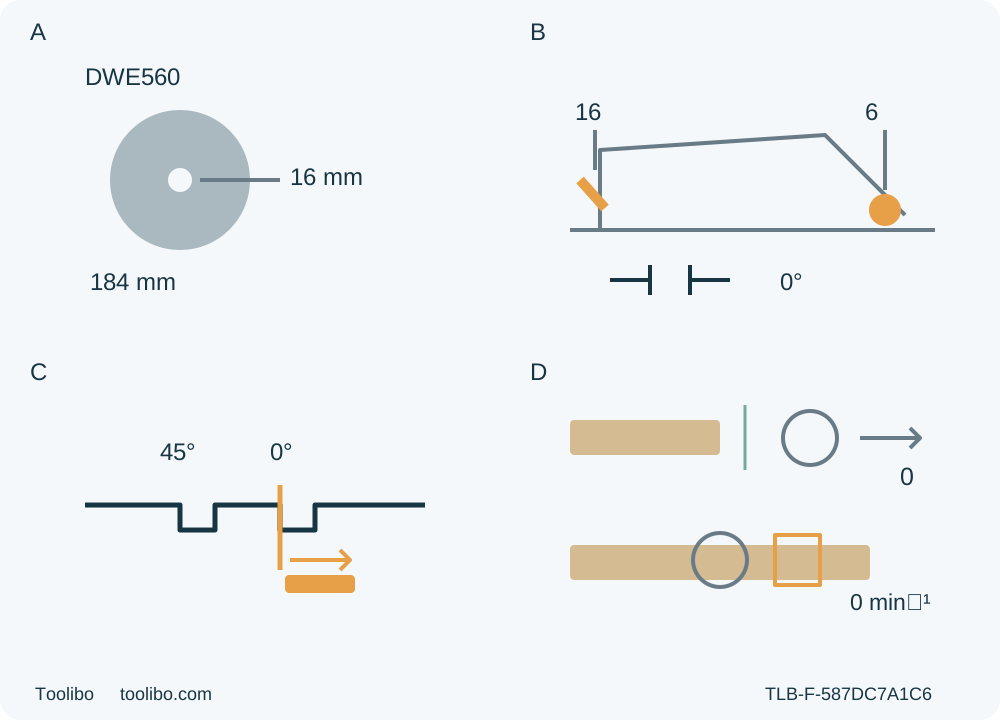
A · Qualify the original assembly
Actual GB Type 1, approved 184/16 EN 847-1 wood blade rated at least the actual tool speed, documented 5500/min; no fitting.
B · Isolate and lock both settings
Unplugged rear depth lever 16 and front bevel knob 6; actual through-cut with about half a tooth and less than a full tooth, supports clear.
C · Read the correct reference
Right zero notch, left 45 notch. Left inner blade edge is the reference; kerf falls right, without a universal offset.
D · Separate finish from interruption
Normal clear exit must retain stable shoe support/two hands before OFF and actual stop before lift. Binding means immediate OFF/motionless hold until stop, never forced withdrawal.
Original conceptual recognition, not to scale or a fixture drawing. All setup is unplugged. B requires about half a tooth and less than a full tooth in the actual stock, not a scale-only setting. C identifies references only: the zero indicator represents the blade left inner edge and kerf falls right. D is not a running-cut sequence or permission to lift a moving blade: normal completion requires clear blade with stable shoe support/two hands before OFF; binding requires immediate OFF and motionless hold until complete stop. Both routes require actual standstill, guard coverage and unplugging before acceptance.
A DeWalt DWE560-GB owner needs more than the right blade diameter. This exact Type 1 system combines a rear depth lever, a front bevel knob, a kerf reference for the blade’s left edge and a mandatory wood-dust extraction arrangement. The following workflow qualifies the original system for one modest square crosscut in known loose wood, including a planned, fully controlled exit and isolated acceptance.
Match the actual UK GB tool and its supply nameplate to the current-linked NB448787 manual, dated 03/26. Its DWE560 column specifies 1350 W, 184 mm blade diameter and 16 mm bore. The adjacent DWE550 and DWE560-XE columns are not interchangeable: neither the DWE550 mounting branch nor the XE bore applies here. A current product field incorrectly saying “Unpowered” is not electrical authority; this is a corded saw. No kit, regional variant or another DeWalt model is counted as this body.
1. Establish original assembly, supply and extraction
The original approved wood blade must already be correctly installed with the proper original washers, bolt and rotation for the actual DWE560. It must be 184 mm/16 mm, comply with EN 847-1 and carry a speed rating equal to or greater than the speed marked on the tool, documented as 5500/min. A matching diameter, tooth count or brand does not establish all those conditions. Unknown approval, unreadable rating, doubtful hardware or a substituted bore means HOLD for qualified clarification, not a trial cut.
Inspect the isolated blade for excessive wear, damage, dullness and deposits, and the accessible tool for broken parts, binding, misalignment, a bent base or loose hardware. Damaged carbide blades must not be used. This guide does not fit a blade, reverse a flange, select a replacement, turn a blade bolt or teach chemical cleaning and sharpening. Original qualified assembly is a prerequisite, not a conclusion inferred from the saw running.
Use the actual GB nameplate’s matching supply. The product describes 240 V mains and the manual includes 230 V and other regional variants; qualify the physical 230–240 V GB configuration rather than transferring a 115 V transformer instruction or another region’s plug. The cord, plug, outlet and any necessary extension must already be sound and suitable for the actual load, length and environment under the complete instructions. Fully unwind a cable reel. Do not modify a plug, select a fuse or repair wiring here. Damaged supply cord requires DeWalt or authorised service replacement. The manual recommends an RCD rated 30 mA or less; that recommendation is not proof that any particular supply is suitable.
Wood cutting requires an appropriate vacuum extractor designed to comply with applicable dust-emission requirements, plus an approved dust mask. The 03/26 manual also requires an officially approved protection class appropriate to the material and local dust rules, source capture, ventilation and a respirator suitable for the dust. Establish those conditions from the actual extractor and material documents; do not invent a universal class letter or numeric suction threshold.
The complete native extraction spout, including its two halves and secure attachment, must already be correctly installed. Use an already qualified direct hose connection or documented DWV9000 AirLock arrangement, not a guessed fit. This workflow does not mount the spout, assemble an adapter or treat the product’s dust blower as extraction. Missing hardware, uncertain protection class, inadequate capture or interference with guard movement means HOLD before cutting.
2. Make isolation and guard checks explicit
Release the trigger, wait for complete blade standstill, switch off and unplug before inspection, adjustment or connection work. A released trigger or automatic lock-off is not physical isolation. Keep the plug visibly disconnected while working on the setup, and isolate the extractor under its own instructions before checking its hose connection.
Before each use, operate the lower-guard lever from fully closed to fully open, then release it and observe return to fully closed. Do this unplugged, keeping fingers clear of teeth and pinch points. Check the spring and confirm free, immediate closure without touching the blade or any other part at all angles and depths of cut; recheck after a drop. A guard that returns slowly, intermittently or incompletely, or contacts any part, requires qualified service before use. Never tie or clamp it open. Check the actual selected depth and angle again after setting them. The ordinary edge-entry cut below uses automatic guard operation, not manual holding open.
Inspect the trigger and lock-off for sound, unobstructed operation with power disconnected. A switch that cannot reliably turn the tool on and off, a defeated lock-off or other known control fault is a service hold. Do not reconnect to reproduce a suspected defect. Remove adjusting keys and tools before connecting power. Keep handles clean, dry and free of oil or grease.
3. Qualify the stock, support and complete exit
Choose clean, dry, untreated loose wood of known identity, approved for the original blade, in a modest size that can be controlled from a stable stance. Inspect the entire route and remaining stock for nails, screws and other foreign material. Exclude hidden services, installed construction, plastics, metal, masonry, abrasive cutting and water feed. This professional tool requires competent use; inexperienced operators need proper supervision.
Work in a clean, well-lit, dry location, without rain, wet conditions or flammable liquids, gases or explosive dust atmosphere. Keep children and bystanders clear. Wear eye and hearing protection, the approved dust mask and appropriate material-specific respiratory protection. Maintain ventilation and active source capture. Secure hair and loose clothing; keep gloves, jewellery and other loose items away from moving parts. Do not proceed if the dust hazard or exposure-control requirements remain unknown.
Place the appearance or “good” face down as the manual directs, without promising perfect finish on either side. Mark the wanted end from a reliable datum and identify waste. Clamp the retained stock to a stable platform, with the wider part of the base supported on the material that will remain. Independently support the future offcut so it cannot sag, twist or close the kerf, while leaving it free to separate. Never hold waste by hand or clamp across the separation. Supports near the cut and outer edges must stay clear of the blade underneath.
Qualify the entire path, not just the starting position: both hands stay on their handles, the base remains stably supported on retained stock, the guard moves freely, and cord, hose and clamps remain clear. Check reach beside or safely above the route while unplugged, blade guarded and teeth clear; do not push an exposed blade through uncut wood as a rehearsal. If using an existing clamped straightedge, establish the actual base-to-cut relationship and clearances rather than copying an offset.
The normal exit is a hard prerequisite. The manual says not to switch on or off with the blade touching material, and also requires complete standstill before lifting from the work. Therefore this workflow requires a genuinely feasible exit where the blade can become fully clear of the material while stable shoe support and two-hand control are maintained, before releasing the trigger. Do not invent a bridge, lift a moving blade or reach past the supported zone to manufacture that condition. If the actual stock and support arrangement cannot satisfy it, HOLD this task and use a different qualified arrangement or cutting system. This paragraph does not certify a fixture from a drawing.
4. Set zero and about half a tooth
Keep the saw unplugged. Loosen the front bevel-adjustment knob 6, set zero on the actual pivot scale and retighten securely. Do not confuse it with the parallel-fence adjustment stud or assume another model’s second bevel fastener. The original blade-to-base alignment must already be correct; this guide does not calibrate it or teach a high-angle cut.
Raise the rear depth-adjustment lever 16 to loosen, position the base using notch 17 on the adjustment strap against the appropriate upper-guard mark, and tighten the lever. For the carbide wood blade, the manual calls for about half a tooth below the wood; its general rule also requires less than a full tooth. Verify the real setting against the actual stock, safely supported with fingers away from the teeth: it must cut through, expose about half a tooth and remain below the full-tooth limit, while clearing supports and clamps. The scale alone is not proof. Recheck after any angle or depth change.
At the front kerf indicator, the actual zero-degree notch is to the right of the 45-degree notch. The indicator represents the left, inner edge of the blade; the kerf falls to its right. Keep the cut on the intended waste side of the mark rather than treating the line as the blade centre. This is not a numerical straightedge offset or a promise of exact dimension. Confirm both locks, line, retained side and the already qualified exit before connecting power.
5. Check active extraction and start clear of the wood
With saw and extractor isolated, check the existing secure spout and hose connection. The hose must not pull the saw sideways, obstruct either grip or restrict the guard at any point. Route the mains cord away from the cut and prevent it catching on the work, clamps or hose. Activate and verify the extractor under its actual instructions before cutting; a connected but idle vacuum is not active capture.
Confirm the trigger is released and the lock-off intact before plugging into the qualified supply. Hold the main handle 2 and auxiliary handle 5 with both hands, using insulated gripping surfaces because contact with the saw’s own cord is a relevant hazard. Keep hands away from the cutting area and underneath the work, without impeding the guard. Position the body to either side of the blade line, not directly in line with it, and maintain a firm stance.
Place the base on the supported retained stock with the blade completely clear of the material. Press lock-off 13, then pull and hold trigger 1. Wait for full speed before entering the wood. Advance smoothly forward with the base flat and the planned guide contact maintained. Let the blade cut without labouring; do not force a slowing tool, twist it to recover a line or release a handle to manage the hose. The lock-off re-engages automatically when the trigger is released; it is not a latch that keeps the tool running.
6. Use the correct finish rule—and the emergency exception
For normal completion, follow the prequalified exit until the blade is fully clear of the material while the base remains stably supported and both hands retain control. Then release the trigger and wait for actual complete standstill before lifting the saw. The spring-loaded guard must close over the blade before setdown. Unplug before measuring, touching cut pieces or altering any connection. Let hot edges cool and handle sharp material carefully. No brake timer or lamp state replaces actual stop.
Binding, a stall, an interrupted cut or a dangerous loss of control is not normal completion. The manual’s explicit kickback rule governs: release the trigger immediately and hold the saw motionless in the material until the blade stops completely. Do not continue driving toward the exit merely to avoid switching off in contact. Do not follow abbreviated “back the saw” wording while the blade is still moving. Never pull a moving blade backward or lift it from a trapped kerf. Isolate before investigating; this guide supplies no restart, forced-release or in-kerf steering procedure.
If the cut wanders, stop and hold through standstill rather than forcing it onto the line. A new route, support arrangement or qualified correction must be assessed separately. An unexplained stall, smoke, unusual noise or repeated loss of straightness is not a harmless sample imperfection to work around.
7. Inspect both result and system
After isolation and cooling, measure from the original reference and check end squareness, straightness, size, both faces, tear-out and burning. Check whether the guide or clamps moved and whether the cord, hose, guard or exit support was compromised. Accept the sample only if it meets the stated project requirement and the whole route behaved normally. The model’s nominal capacity does not certify a particular support, finish or tolerance.
Record any failure and HOLD the next cut until the cause and remedy are properly established. A small loose offcut is not a safe platform for repeated corrective trimming. Do not adjust blade alignment or use a powered test to diagnose suspect hardware under this guide.
With the plug disconnected, keep accessible housing and vents clean using the manual’s dry, soft non-metallic brush or suitable vacuum approach, wearing eye and dust protection. Non-metallic surfaces may be wiped with a cloth dampened only with water and mild soap, without liquid entering the tool. No solvents, immersion, internal air-blast cleaning, blade-removal cleaning, sharpening or gearcase service is taught here. Guard faults and other repairs go to qualified service. Store the isolated tool securely, retaining its exact instructions and the sample’s ready-or-hold record.
Models referenced