
CMES510 isolated qualification checkpoints
Four conceptual panels show the conditional 120 V 15 A cord reference, original 184 mm blade rated at least 7000 rpm, separate depth 12/13 and bevel 9/14 controls, and a disconnected cord.
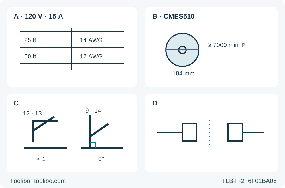
A · Actual supply
For verified 120 V 15 A only, minimum 14 AWG at 25 ft and 12 AWG at 50 ft; the same row does not recommend 100 or 150 ft. Never substitute this for actual nameplate and cord checks.
B · Blade, not motor
The retained original approved 184 mm blade requires at least 7000 rpm rating and the actual warning-label constraints; 5500 rpm motor speed does not lower that requirement.
C · Independent locks
Unplug before using rear depth lever 12 with scale 13 and front bevel lever 9 with scale 14; set less than a full tooth and zero bevel, then secure both.
D · Physical isolation
Release the trigger, wait for full standstill and guard coverage, set down safely and unplug before inspection. No electrical repair or circuit-reset step is shown.
A applies only to the verified 120 V 15 A case; total length and every extension still require the full manual table and condition check. B is original-assembly qualification, not fitting. C identifies independent controls on an unplugged tool, not their scale position. D is physical disconnection, not a zero-speed substitute.
A suitable extension cord is only one part of preparing a CRAFTSMAN CMES510 for work. This owner workflow connects the actual supply decision to the original blade assembly, guard inspection, independent settings, supported route and finished-sample acceptance. It is for a manageable square edge-entry cut in known loose wood, not an electrical repair or a maximum-capacity demonstration.
Match the actual US CMES510 and its supplied instructions to N638218, dated 08/18. The current US manufacturer page directly links the QU/CMES510/1 document route. That route identifies the selected Type 1 documentation; it does not establish the physical type of a tool whose nameplate has not been checked. Do not substitute a Canadian document route, the CMES500 or a cordless CRAFTSMAN body.
Qualify the original assembly before planning power
Require the already correctly installed, manufacturer-approved original wood blade, washers and retaining hardware, with a known service history. The manual specifies 7-1/4 in / 184 mm and a 5/8 in / 16 mm bore. Its blade-use section explicitly requires a blade rated for 7000 rpm or higher. The separate 5500 rpm motor specification does not reduce that blade requirement. Also satisfy the warning-label accessory rating and the requirement that the accessory rating be above the actual tool speed.
These facts identify an acceptable existing assembly; they are not a replacement recipe. Do not remove a diamond knockout, guess washer orientation or borrow a tightening direction from another saw. A dull, damaged or unidentified blade, unusual mounting parts or evidence of improper work means hold for the complete exact instructions and qualified correction. The current product’s 18-tooth package listing and related 24-tooth blade link do not guarantee the contents or approval of an owner’s actual assembly.
There are two other source limits worth keeping visible. The current product feature lists a 2-1/8 in capacity, while the manual’s table gives 2-1/2 in at zero and 1-7/8 in at 45°. This task does not reconcile those into a promised maximum. Choose modest stock for which actual depth, clearance and support can be established. The product’s structured “Integrated Batteries” field conflicts with its corded identity and the manual; it is not evidence of a battery mode.
Make a real supply and cord decision
Before any connection, check that the actual supply agrees with the nameplate. Inspect the tool cord, plug and intended extension while disconnected. Cuts, damaged insulation, loose or damaged fittings, suspect switch behavior or an unknown supply are reasons to stop, not invitations to energize the tool and reproduce a fault. Cord or switch repair belongs to the appropriate authorized service route. Do not modify a plug to fit an outlet.
Use the manual’s extension table with the actual voltage, total length and nameplate current, not just a cord’s color or apparent thickness. For a verified 120 V, 15 A setup, the more-than-12 through 16 A row gives minimum 14 AWG at 25 ft and 12 AWG at 50 ft. At 100 ft and 150 ft that row says not recommended. A lower AWG number means a heavier conductor. These are the exact conditional table entries, not universal limits for every voltage or an approval of an otherwise damaged cord.
If multiple extensions make up the total route, the manual requires each one to meet at least the minimum wire size for that total length. Do not treat two shorter cords as two separate shorter electrical runs. Prefer a suitable arrangement whose total length and markings can actually be verified. Outdoors requires an outdoor-suitable extension. This particular sample is dry work; the manual’s GFCI condition for unavoidable damp operation is not a reason to proceed with wet wood or wet conditions that its intended-use section excludes.
Plan the cord away from the cut, hot or sharp surfaces, pinch points and walking routes. Leave enough controlled freedom for the whole feed without a connection pulling tight or a loop catching the guide. Do not carry or unplug the saw by pulling its cord. If a practical compliant route cannot reach the work, move the work or supply arrangement; do not improvise an electrical modification. Fuse replacement, breaker resetting, voltage measurement and circuit repair are outside this workflow.
Inspect the isolated saw and prepare the material
Keep the trigger released and the plug physically disconnected for checks and settings. Use lower-guard retracting lever 7 to check free movement and release it to verify immediate complete closure. The guard must not touch the blade or another part at any angle or depth of cut; check its spring as well. A slow return, deposit, bent part or uncertain condition requires service before use. Do not tie the guard back or perform a powered guard-fault trial.
Use dry, untreated, nail-free wood of known composition and inspect the full intended route for foreign material. The intended-use section excludes metal, plastics, concrete, masonry, fiber cement, water feed and abrasive wheels. A later warning about heat while cutting plastics is not authorization to override that exclusion. This task also excludes stacked sacrificial backers, internal pocket cuts and installed hidden work.
Provide ventilation and appropriate NIOSH/OSHA-approved respiratory protection for the dust exposure. Wear ANSI Z87.1 eye protection (CAN/CSA Z94.3) and ANSI S12.6 (S3.19) hearing protection; ordinary spectacles are not safety glasses. The general instruction to connect dust collection where provided does not establish a dedicated port, adapter size or vacuum retrofit on this exact body. Do not invent one or borrow another manufacturer’s airflow thresholds. If the actual workspace cannot manage the dust, postpone the cut.
Set and lock the two adjustments independently
With the saw unplugged, loosen rear depth lever 12, move shoe 4 to the intended position using depth scale 13, then tighten the lever. Confirm that less than a full tooth projects below the actual work. Another paragraph mentions one tooth, but the explicit depth procedure and general safety rule use less than a full tooth; follow that stricter actual setting here. Check underside clearance along the entire cut and verify that the shoe cannot shift.
Loosen front bevel lever 9, set zero on bevel scale 14 and secure the lever. One sentence in the manual calls the final control a knob, but the component list and Figure G identify lever 9; do not search for an imaginary second part or assume an unsupported turning direction. The 22.5° and 45° detents and wider bevel range are not needed for this square sample. Zero on a scale still needs a square result check, not an experimental calibration.
Arrange support, guide contact and a clear route
Measure and mark the wanted dimension and waste side. Clamp the retained work to a strong, stable, level support. Both portions need independent support near the cut and their edges, outside the blade path. The wide part of the shoe stays on the retained supported portion, not the waste that separates. Do not hold the offcut, work on a leg or use an end-only arrangement that lets a long panel sag and pinch the blade.
For ripping, use the prescribed rip guide or a securely clamped straightedge. This task chooses an existing suitable straightedge rather than commissioning an unspecified accessory. Establish the actual blade-to-contact-edge offset with the same original assembly and zero setting on scrap. Do not import a dimension from another CRAFTSMAN body or treat a pencil line as a calibrated kerf edge.
Check entry, middle and exit for continuous shoe support, clamp clearance, cord freedom and a comfortable two-hand stance. Assess reach beside or safely above the route while unplugged, guard closed and teeth clear; do not drag the projected blade through uncut stock as rehearsal. Waste must remain free to separate without closing the kerf. If completion needs an assistant to catch it or a mid-cut support change, redesign the layout first.
Make and accept the supported sample
After all isolated checks pass, confirm OFF and connect the qualified supply. Hold main handle 2 and auxiliary handle 3 with both hands, using insulated gripping surfaces for the own-cord contact hazard. Keep your body beside rather than in line with the blade, hands clear of its underside and guard. Place the shoe on supported work with the blade clear of the wood.
For an otherwise sound tool only, perform the manual’s normal on/off check before cutting: with the plug connected, lower guard closed, blade clear of any material and both hands controlling the designated handles, deliberately operate and release the trigger. Wait for complete standstill before positioning for the sample. This is not permission to reproduce a suspected cord, switch or guard fault; any such concern remains a service hold, and unexpected behavior ends the check rather than prompting repeated tests.
Depress trigger 1, allow full speed before entry and feed forward with gentle pressure while keeping the shoe in full contact. There is no lock-on provision; never tie or block the trigger. Do not force a slowing saw or twist it back onto a missed line. Unknown noise, abnormal operation or loss of control means stop, not another trial to establish whether it repeats.
For binding or any interruption, release the trigger and hold the saw motionless until the blade completely stops. Never pull a rotating blade backward from the kerf. Unplug before investigation; restarting an interrupted kerf is not taught here. At normal completion, release the trigger, wait for complete standstill before withdrawing, verify lower-guard coverage and place the saw safely before unplugging to measure. No electric-brake time or timed lifting permission is established by these sources.
Measure the intended dimension, edge straightness, square cut and finish. The manual recommends the finished surface underneath to reduce splintering; qualify that choice on the actual trial rather than promising perfect edges. Also require a process pass: both levers stayed locked, the guide did not shift, the cord stayed clear, the shoe remained supported and the waste separated without pinching. A good-looking piece does not certify the tool’s overall health or excuse a supply fault.
Keep the accepted setup record with the actual blade identity, supply and extension markings, depth, zero setting and guide relationship. Store unplugged, securely and out of reach of untrained users. Cleaning, brush work, cord repair and other service must follow the complete manufacturer instructions and their qualified-service boundaries; this guide supplies no compressed-air or solvent recipe. Do not use the hang hook as a body tether or overhead suspension. Resolve any damaged part or abnormal behavior before further work rather than treating an accepted sample as permanent clearance.
Models referenced