
Four GC checks before the sample
A shows a removed battery and a depth button; B shows two separate bevel locks at zero; C compares two-level and six-level default speed tables; D shows a 35 mm extraction connection and separate status symbols.
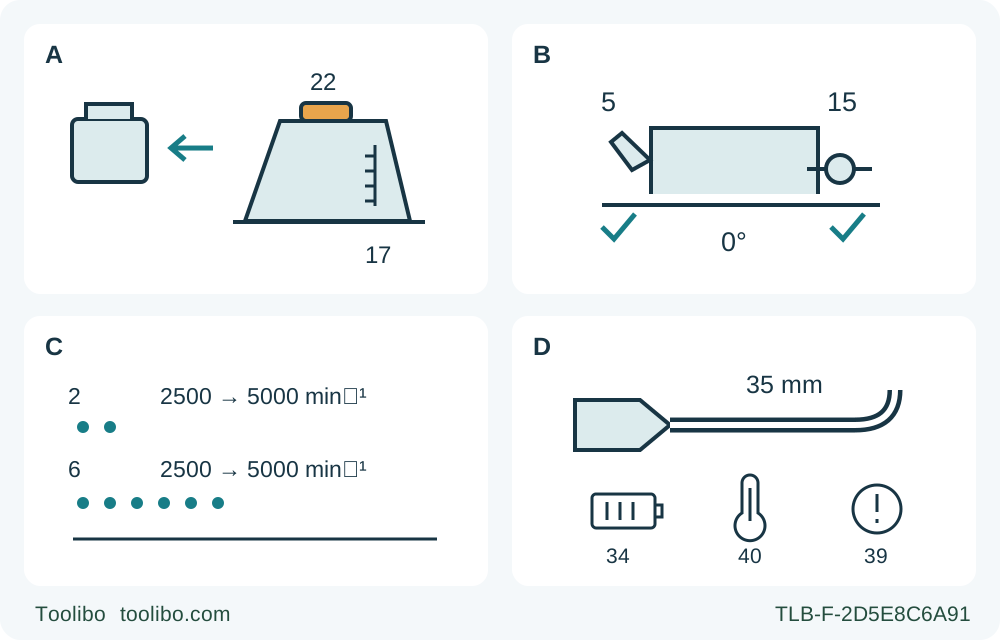
A · Isolate and set GC depth
Remove the battery; use button 22 and scale 17, with less than one full tooth below the work. Confirm that the setting holds.
B · Secure both GC bevel locks
With the battery removed, establish zero on scale 7 and secure lever 5 and wing bolt 15. Do not use the C-only single-lock instruction.
C · Establish the actual configuration
The default two-level table is 2500/5000 rpm; six levels span 2500–5000 rpm. Unknown prior programming means hold, not a guessed speed or reset.
D · Qualify extraction and read the correct signal
Use the actual suitable 35 mm hose system for this workflow. Distinguish battery bars, temperature and overall status; a warning stops the sample workflow rather than authorizing a reset.
This is a controls-only conceptual diagram, not a blade-fitting or running-cut layout. A requires battery removal before depth adjustment. B represents both GC bevel restraints, not their physical locations. C shows why the same displayed level must not be assumed to mean the same speed in every configuration; the numbers are documented default endpoints, not a universal wood setting. D separates extraction from battery, temperature and tool-status indications. It depicts neither an installed airflow test nor a protective-reset sequence.
This workflow prepares an existing Bosch GKS 18V-68 GC for one supported, square, edge-entry wood cut using a securely clamped auxiliary straightedge. Its outcome is a sample with an accepted dimension, square edge and controlled cutting behavior—not proof of maximum capacity or a demonstration of the connected features. It applies to the UK product 06016B5171, type 3601FB5101, matching the current-linked 1 609 92A 7RA instructions dated 6 July 2022. A current download link does not establish that every owner’s supplied revision is identical.
The GC and C share a manual but not every control. The GC has a depth button, an additional bevel lock and a user interface; even the numbered cut marks differ. Read the actual nameplate and controls before using this guide. It does not commission a guide rail, program an app, change the blade, charge a new battery system or explain recovery after a protective shutdown.
Establish the existing system before choosing the sample
Require the complete matching tool instructions and an already commissioned, manufacturer-approved genuine battery and charger combination with its own complete instructions. Confirm that the actual pack is sound, suitably charged and correctly retained. Product-family advertising is not a substitute for the actual approved pairing, and a kit photograph does not prove what an owner received. This article does not specify a new charging sequence or transfer another Bosch saw’s battery requirements.
Keep the correctly installed original wood-blade assembly. The manual’s regional table for 3 601 FB5 10. gives a 30 mm bore, a blade diameter range of 184–190 mm and body thickness of 1–2 mm. Other table columns have different bores; they are not conversion options. The blade must meet the wood-blade requirements, including EN 847-1, be suitable for the actual wood and have a permitted speed higher than the tool’s maximum 5000 rpm, satisfying the stricter wording in the blade instructions. Uncertain identity, damage, unsuitable teeth or an unexplained flange arrangement means stop for the complete instructions and qualified correction. Do not infer that turning a speed setting down makes an incorrectly rated blade acceptable.
Choose clean, loose, known wood without concealed fasteners or suspect coatings. Select a manageable sample within the actual original blade’s capability and the tool’s verified square-cut depth. The nominal 68 mm maximum does not prescribe a useful sample thickness. There is no metal, masonry, plastic or internal-plunge authorization here.
Know the speed configuration instead of guessing a number
The GC’s basic configuration has six speed settings plus ECO. The manual also permits an app to program two to six levels. Consequently, a displayed level is not a universal speed: the default six-level table runs from 2500 to 5000 rpm, while the default two-level table has only 2500 and 5000 rpm. The same level number cannot be transferred blindly between configurations.
Use only an existing, known, documented configuration and a speed appropriate to the installed blade and wood under the complete instructions. Record that setting for the sample. If a previous owner changed the configuration and its meaning is unknown, hold the task until the configuration is properly established; do not invent a factory reset or assume the display proves a particular rpm. ECO is a separate mode, not a substitute for blade qualification. This workflow does not promise a runtime saving or prescribe one unsupported speed for every wood.
If a GCY 42 module is fitted, its complete instructions and applicable radio restrictions remain prerequisites. Not opening an app does not prove the radio is absent or inactive. Unknown module status or incompatible surroundings must be resolved before operation; module removal and programming are outside this task.
Isolate, inspect and set square depth
Release the trigger and wait for complete blade standstill before isolation. Press battery release button 30 and withdraw the battery completely without force; the pack has two retention levels, so partial release is not removal. Complete this isolation before adjustments, inspection, guide placement or clearing the tool. Wear eye and hearing protection and appropriate respiratory protection; provide ventilation and material-suitable extraction. Keep the tool stable and fingers out of the tooth path. Check that the lower guard moves freely, closes immediately and does not contact the blade or other parts at all angles and depths of cut. A damaged, slow or binding guard requires correction before use; do not tie it open or test it by running a faulty saw.
On the GC, cutting depth uses button 22 and scale 17, not the C model’s lever 23. With the battery removed, use the depth button to set the assembly: moving the saw away from the base reduces depth, while moving it toward the base increases depth. Set less than the height of one full tooth visible below the workpiece. Confirm that the selected position holds securely before reconnecting power. If the button or retention does not work as described by the actual supplied instructions, do not improvise an additional locking action or use the saw.
For the GC’s square setting, identify both bevel restraints: adjusting lever 5 and wing bolt 15. With the battery removed, release them as required, set zero on scale 7 and retighten both. The C-only single-lever instruction is not sufficient for this body. Recheck depth, guard freedom and the square setting after adjustment; a scale reading alone is not the final cut-acceptance test.
Qualify extraction without borrowing a different manual
Chip ejector 18 rotates freely. The 7RA instructions allow a 35 mm extraction hose or the specified dust/chip box at that ejector. This workflow chooses a connected, material-suitable extraction system with its own operating instructions. Especially hazardous or carcinogenic dry dust requires a special suitable extractor, and the manual specifically requires extraction for beech and oak. Ventilation and appropriate respiratory protection remain necessary; collecting visible chips does not certify exposure control.
Do not import another model’s adapter diameter, prohibition on a collection box or installed airflow threshold. Those requirements must come from this exact system’s applicable documents. With the battery removed, check the actual connection and route the hose so it cannot pull the base off its guide, foul the guard or enter the blade path. Keep the ejector clear under the prescribed maintenance instructions. If effective extraction or a safe hose route cannot be established, change the arrangement or hold the cut rather than treating the hose as optional decoration.
Lay out a complete supported path
The manual permits a securely fastened board or rail as an auxiliary guide, with the base following it. Here that means a straight, rigid straightedge clamped to the workpiece—not direct engagement with a proprietary guide-rail groove. Qualify the reference edge and calibrate the actual blade-to-contact-edge offset on comparable scrap. Do not use an assumed factory offset.
For this GC away from a guide rail, zero-degree cut mark 8 identifies the square blade position; mark 9 is the 45-degree reference. The C’s numbering is reversed. Use a test cut to establish the actual kerf relative to the wanted line and guide contact. Neither a printed line nor a nominal mark width is a guaranteed finished dimension.
Clamp the retained work securely. Support both retained and waste portions outside the blade path so the work cannot sag and close the kerf; the waste must be able to separate without being trapped against the blade. Keep the broad retained base supported throughout entry, travel and exit. Confirm clearance under the entire projected cut, including the final tooth exit. The guide clamps, hose, supports and nearby objects must all remain clear.
With the battery still removed, assess stance, reach and both designated grips beside or safely above the intended path, with the blade guarded and no tooth contact. Do not push projected teeth through uncut wood as an isolated rehearsal. If the far end cannot be reached with stable footing and full control, rearrange the work before starting. Never plan to move a clamp or support during the cut.
Make and accept the normal sample
After all isolated checks pass, ensure the trigger is released, reconnect the qualified battery and establish the documented setting. Use the insulated main and auxiliary handles with both hands; keep your body to either side of the blade line rather than directly behind it. Keep hands away from the underside and ejector. Start with the blade clear of the work: press lock-off 1, then hold trigger 2. Allow normal running speed before controlled entry, and guide the saw evenly forward with gentle pressure and continuous base contact.
Do not force feed to overcome resistance. If binding or an abnormal condition occurs, release the trigger and hold the saw stationary until the blade stops; do not pull a moving blade backward from the kerf. Isolate before investigating. This article does not prescribe a protective-reset sequence, a live cooling run or restarting within an old cut.
At normal completion, release the trigger, retain control until complete standstill and guard coverage, then set down safely and remove the battery before inspection. Check the finished dimension at the intended references, squareness, edge condition and whether the guide remained fixed. Reject the process if the base lost support, the work moved, the kerf pinched or the hose interfered, even if the dimension happens to look right.
The charge bars, temperature indicator and overall tool-status indicator are different displays. A red or yellow indication is not a cutting instruction, and flashing red overall status denotes restart protection in this manual. Stop the sample workflow and consult the exact indicated condition and complete instructions; a green status is not a certificate for guarding, support or assembly. Record the accepted setup only when both the work result and the process pass. Brush away accessible dust with the battery removed as instructed, keep vents and the guard area clear, and store the isolated tool without improvising blade cleaning or service procedures.
Models referenced