
Four checks for the documented UK GKS 190
A shows an extractor connected through a 35 mm hose to a highlighted tool-end point, with required 230 mbar and 36 L/s minima. B separates depth lever 24 from bevel bolts 6 and 26. C uses the left edge of zero mark 9, waste right. D is an isolated upward-feed plan with blade right, broad retained support left and neutral contacts at both grips.
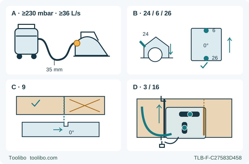
A · Qualify installed extraction
Verify at least 230 mbar and 36 L/s at the tool connection; connect the correct adapter only to external extraction, never a dust bag.
B · Lock three settings
Unplug, secure depth lever 24 with less than one full tooth exposed, and tighten both zero-bevel bolts 6 and 26.
C · Use the zero mark’s left edge
Use mark 9 for the square cut with waste right, then confirm the actual kerf and retained dimension on scrap.
D · Isolated supported rehearsal
Keep the broad base on retained support, both grips available, and the hose, cord and clamps clear of the full travel.
All setup and the D rehearsal are unplugged and stationary. A locates the required vacuum and flow at the tool connection, not the extractor outlet or free-air motor rating; 35 mm is the recommended hose nominal diameter. B requires depth lever 24 and both bevel bolts 6/26 secure. C aligns on the left edge of 0° mark 9 with waste on the right, then verifies the real kerf by sample. D represents intended upward travel, right-side blade and supported retained base to the left; the two neutral contact dots identify grips 3 and 16, not hand movement near a running blade. No panel illustrates blade replacement.
Match the UK body before using a familiar model name
A Bosch GKS 190 owner needs to identify the regional body, not just the name on the guard. This workflow uses the existing UK product 0601623070, machine type 3 601 F23 070, with an original correctly fitted wood-blade assembly. Its outcome is a supported square wood sample using the correct depth and bevel locks, the left edge of the zero cut mark and a qualified external dust-extraction connection.
Read the complete Bosch D21 operating manual, 1 609 92A D21 dated 19 September 2025, and compare it with the actual tool and supplied instructions. The manufacturer-hosted E52 UK declaration expressly identifies type 3 601 F23 070. The current UK product identifies the 240 V offer, but its rendered download section does not establish a direct link to the D21 tool manual. We therefore use an exact document-scoped owner workflow, not a claim that D21 is the booklet supplied with every current box.
The two technical columns in D21 are not interchangeable. Type 3 601 F23 0.0, which includes this 070 body, has a 30 mm bore, a 190 mm maximum blade diameter and a maximum blade-body thickness of 2.0 mm. The other column lists a 184 mm maximum and a 16 mm bore. Do not borrow that other region’s blade dimensions, flange arrangement or cutting capacity simply because both columns say GKS 190.
Retain the qualified original assembly
Unplug before inspection. The documented body has a 1,400 W input and 5,500 rpm no-load speed. Retain the approved original wood blade and correctly positioned mounting flange, clamping flange and bolt. The blade must match the tool and instructions, be sharp and undamaged, and be tested and marked to EN 847-1:2017. D21’s fitting section calls for a permitted blade speed higher than the tool’s no-load speed, as well as at least the maximum speed marked on the tool; do not accept a blade below either requirement.
A critical limitation remains in the exact source: the English removal and tightening instructions both refer to rotational direction ②, while Figure A shows opposed directional arrows. This article does not silently repair that contradiction, infer a thread direction from another Bosch saw or supply a replacement procedure. The original correctly installed assembly is a prerequisite. If a blade has been changed, the mounting is uncertain or replacement is required, stop for Bosch clarification or qualified service with the complete matched instructions before continuing.
Do not fit an HSS blade, abrasive wheel or a blade intended to cut ferrous metal. Do not modify the saw into a stationary table machine or work overhead. Generic safety language about special cuts is not a complete plunge-cut setup, and no internal plunge workflow is offered here. The sample uses known, untreated wood with no nails, screws or concealed objects in the path.
Check the lower guard and its spring with the plug removed. The guard must move freely and close immediately, without touching the blade or another part at all angles and depths of cut. Never clamp or tie it open. A slow return, damaged spring, bent guard or uncertain mounting means no cut, even if the motor still runs normally.
Treat extraction performance as an installed-system requirement
Wear eye and hearing protection for the sample cut. D21 says not to work without dust-reducing measures and requires suitable breathing protection and ventilation. This sample uses external extraction appropriate for the wood. Dust from beech and oak is specifically identified as especially harmful; the manual requires extraction for those woods. Avoid unknown coatings and treated material rather than trying to solve an unassessed dust hazard with a generic vacuum.
With the tool unplugged, push the correct adapter 23 onto chip ejector 14 until it clicks into place. The adapter must only be fitted when an external extraction system is connected. Do not leave it as a bare outlet extension, and do not attach a dust bag to it: both restrictions are explicit because the extraction path can clog. A general paragraph mentioning dust boxes or bags does not authorize a bag on this adapter.
The recommended hose nominal diameter is 35 mm. The required performance is at least 230 mbar vacuum pressure and at least 36 L/s flow at the power tool’s extraction connection. These are not the extractor motor’s free-air headline ratings. Confirm that the complete compatible extractor, hose, adapter and filter arrangement meets the tool-connection requirements using the relevant system documentation or appropriate verification. If that cannot be established, do not describe the setup as qualified.
Bosch recommends dust class M filtration; the collector must also suit the actual material and its hazards. Route the hose without a sharp obstruction, snag or sideways pull on the saw, and follow the extractor’s instructions. If suction falls, stop and eliminate the cause before resuming. Keep the adapter clean and do not put fingers into the chip ejector. Extraction reduces exposure but does not replace personal protection, ventilation or housekeeping.
Set support, depth and both bevel locks
Clamp the work to a stable platform. Mark the retained dimension and waste side, keeping the larger supported portion under the broad part of the base as the cut finishes. Support a panel on both sides near the cut and near the outer edges, while leaving the whole blade path clear underneath. The offcut must not fall into the blade, close the kerf or require a hand to catch it.
Keep the tool unplugged while adjusting depth. Release clamping lever 24, move the saw relative to base plate 12, read scale 25 and retighten the lever. Set the actual projection below the work to less than the height of one full tooth. Maximum capacity is not a setting for a thin sample. Check that the locked depth cannot shift.
This lever can be repositioned on its mechanism if adjustment travel or clamping becomes inadequate; that is not a reason to force a partly locked setting. If the ordinary setting cannot be secured, use the complete correction instructions or qualified service rather than improvising during the cut.
Zero bevel requires both wing bolts: front 6 and rear 26. Release them while unplugged, establish zero on angle scale 5, then retighten both. Checking only the visible front bolt leaves an incomplete setup. Bevel reduces the effective depth relative to the depth scale, but this sample remains square and does not rely on an angled-capacity claim.
Use the correct side of the cut mark
The 0° mark is number 9; the 45° mark is number 8. For this square cut, guide on the left edge of the zero mark, with waste on the right, as shown in the actual D21 cut-mark illustration. Do not center a pencil line in the notch by habit or swap the two identifiers because another Bosch model uses different numbering.
Make a scrap test to establish the actual kerf location. A cut mark indicates the blade’s path, but blade width still determines where the finished edge falls. Measure the retained sample and correct the guide position while unplugged before cutting the project stock. Do not twist a running saw toward a line that was laid out incorrectly.
For a parallel-edge cut, feed the matching parallel guide 10 through the base, set its scale at the corresponding zero cut mark and tighten wing bolt 7. It needs a straight, sound reference edge. For a larger piece, Figure E supports clamping a straight board or rail to the work and guiding the base against it. That is an auxiliary straightedge, not permission to engage the saw directly with a proprietary guide-rail track. The current product table says guide-rail compatibility is not provided.
Check every clamp against the full base, housing and grip path. The guide cannot obstruct the lower guard or pull the saw out of alignment. Keep the hose and mains lead independently clear of the blade, clamps and walking route. The conceptual figure uses upward intended travel, a right-side blade and retained support to the left, matching the actual operating perspective; it is a disconnected planning view, not a running-cut pose.
Check the supply and starting controls
Use the actual nameplate voltage and frequency, an intact original plug and an appropriate supply. This article’s current UK product identity does not authorize a 110 V substitution or a do-it-yourself plug change. A damaged cord or unsuitable plug needs the manufacturer’s specified service route. Keep the work area dry and observe the full electrical safety instructions, including appropriate RCD protection where the stated conditions require it.
The start sequence is lock-off switch 2 followed by pressing and holding on/off switch 1. Release switch 1 to stop. It cannot be locked on and must remain pressed during operation. The lock-off reduces unintended starting but does not isolate the electrical supply; unplug for all settings, inspections, cleaning and accessory work.
While unplugged, rehearse the approach and clearance with both insulated grips available: auxiliary handle 3 and main handle 16. Keep the body to one side of the blade’s line and neither hand underneath the work. If maintaining the guide contact requires reaching across the blade or letting the base tip, change the layout rather than attempting the cut.
Make the sample and respond to a problem
After the work, settings, guide, supply and extraction have all been checked and the trigger is released, connect power. Place the front base on supported material with the blade clear of the entry edge. Hold both grips, start the tool and let it reach operating speed before entering the wood. Feed forward gently and uniformly, keeping the base flat and the blade speed steady. Pressure that forces the motor to slow is not a way to compensate for a dull blade or poor support.
If the blade binds, the line is lost or the cut must be interrupted, release the switch and hold the saw motionless until the blade stops completely. Do not pull a moving blade backward or lift it out of the kerf. Unplug before investigating support, alignment, depth, blade condition or a snagged hose. Correct the cause before another attempt. When an appropriate restart in an existing kerf is possible, center the blade and ensure its teeth are not engaged in the wood.
At completion, keep control, release the switch and wait for full standstill. Confirm that the lower guard covers the blade before setting the tool down or handling the offcut. This guide does not invent an electric brake, instantaneous stop or soft-start behavior from marketing. The observable stop and functioning guard are the conditions that matter.
Accept and maintain the whole setup
Unplug before measuring retained width and squareness. Check whether the guide, clamps or supports moved, whether the offcut behaved as planned and whether extraction remained effective. A straight-looking edge does not excuse a loose rear bevel bolt or a guard that failed to return. Correct setup faults while isolated and repeat the sample if needed; persistent mechanical or electrical faults require service.
Keep the tool and ventilation slots clean. Remove dust and chips around the retracting guard with a brush so its automatic movement remains free. Do not turn this care step into an improvised blade-removal or chemical-cleaning procedure. Bosch or an authorised service centre must replace a damaged supply cord. Store the tool unplugged with the exact instructions, and record the accepted depth, guide reference and extraction arrangement for the next comparable cut.
Models referenced