
Four model-specific checks before the sample
A shows the original 165 mm blade with 20 mm bore and rating above 5000 rpm. B separates depth lever 7, less-than-full-tooth projection and single zero-bevel lever 9. C shows an extractor connected by hose to a saw with the measurement point at the saw end, requiring at least 230 mbar and 36 l/s. D shows the left edge of the zero-degree mark and right-side waste.
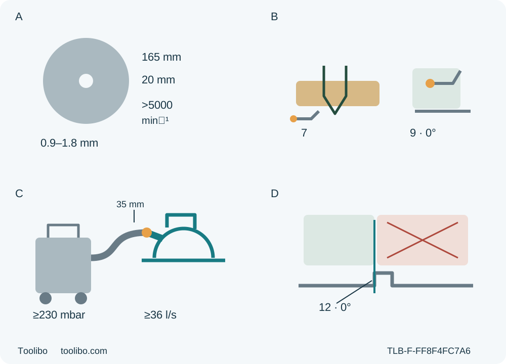
A · Match the original blade
Confirm the actual original wood blade and condition, 165/20 mm, body 0.9–1.8 mm and rating strictly above 5000 rpm. Unknown approval or assembly holds the task; no fitting is taught.
B · Isolate and lock the settings
Remove the battery completely. Set actual through-cut depth with less than a full tooth below stock using lever 7; secure zero bevel with the separate single lever 9 and check both locks.
C · Verify installed extraction
Require at least 230 mbar AND 36 l/s at the tool connection with the actual hose/filter/system. Operate the suitable extractor under its own instructions and stop if suction falls.
D · Keep the correct retained side
Use the left edge of 0° mark 12 with waste right, not the adjacent L model geometry. Qualify the clamped-straightedge full base/guard/clamp/hose path and verify the isolated sample.
These are isolated conceptual checks, not a fitting procedure or running-cut pose. A also requires actual wood approval, 0.9–1.8 mm blade body and the prescribed marking. B shows only part of a tooth below the stock, not a scaled depth setting. C requirements apply at the tool connection with the actual system installed; 35 mm is the recommended nominal hose, not a performance guarantee. D is the non-L right-blade marking convention; the guide offset and finished size still need the actual sample.
This workflow is for the UK GKS 18V-57-2, order 06016C1200 and actual body 3601FC1200, under Bosch’s D1P operating manual dated 20 April 2026. It ends with one ordinary square edge-entry sample guided by a securely clamped straightedge, followed by an isolated dimensional and process check. It is not a guide-rail installation, blade replacement or battery commissioning tutorial.
Match the actual nameplate, right-blade body and controls before proceeding. The manual also covers the left-blade GKS 18V-57-2 L; its illustration is not interchangeable with this one. The current product address retains an older “185 LI” name in its URL, but the displayed order, actual body number and E3J UK declaration identify the selected 57-2. That does not establish equivalence with an older saw supplied under another name. If the tool or complete instructions do not match, hold the task.
Establish the original blade and power system first
The current UK product identifies the original Standard for Wood blade 2608837685: 165 mm diameter, 20 mm bore, 24 teeth, with the listed 1.5/1.0 mm cutting-width/body dimensions. Positively identify the actual installed original blade and its approval for the chosen wood. Do not assume an old box, a similar label or an unknown replacement proves the assembly.
D1P specifies a 165 mm blade, 20 mm bore and blade-body thickness from 0.9 to 1.8 mm. The blade’s permitted speed must be higher than 5000 rpm, not merely equal to the saw’s no-load figure; European blades must meet the specified EN 847-1 marking requirement. Unknown identity, rating or material suitability is a stop condition. The generic accessory page’s FiberCement family does not expand this wood-only task to cement or masonry. HSS blades, abrasive wheels and ferrous cutting are excluded. This workflow keeps the correctly installed original blade, flanges, washer and bolt; it supplies no fitting direction, torque or partial service recipe.
Use only an actual, sound, already commissioned GBA 18V 5.0 Ah battery and its documented specified charger within D1P’s listed system, with the complete battery and charger instructions available. The manual’s broad family table is not a procedure for commissioning an arbitrary pair or a promise about carton contents. First-use full charging must already have been completed under those instructions. Do not use damaged or modified packs, and do not open or repair them. Keep terminals away from loose metal, and protect the pack against water, excessive heat and impact.
The manual permits operation and storage from −20 to +50 °C, with limited performance below 0 °C; the 0 to +35 °C charging range is a different context and is not a charging lesson here. The 5000/min figure was measured at 20–25 °C with GBA 18V 5.0 Ah, not guaranteed as actual loaded cutting speed or runtime. Charge indication is checked only while the tool is not operating; an absent indication or abnormal pack condition is not something to resolve by repeatedly pressing the saw’s trigger.
Isolate and inspect before every setup
Release the trigger, wait for complete blade standstill, then press battery release 21 and withdraw the pack completely without force. There are two retention levels; a partly released battery is not isolated. Keep it out for all inspection, depth, bevel and guide adjustments.
Check the housing, handles, base, switch, locks and original accessible mounting hardware. The blade must be sharp, clean, undamaged and appropriate for the wood, with no loose or incorrect washer/bolt, binding, misalignment or unexplained contact. A defective switch, a damaged or modified tool, or an uncertain dropped-tool condition requires qualified correction before use. Remove any adjusting key before reconnecting power. Do not test a suspected fault by running the saw.
Before each use, operate the lower guard with its retracting lever 16 while isolated. It must move freely, close instantly under its spring and clear the blade and other parts at all angles and depths of cut. Pay particular attention after a drop. A sluggish, bent, sticking or damaged guard or spring needs service before use. The lower guard operates automatically during the ordinary edge-entry cut in this guide; never tie it open or hold it open to make the sample. Hands stay away from the blade, underside of the stock and chip ejector.
Qualify extraction at the tool connection
This task selects active external extraction, not the optional dust box. D1P requires the installed system to deliver at least 230 mbar vacuum and at least 36 l/s airflow at the power tool’s extraction connection; 36 l/s is 129.6 m³/h. Both conditions matter. An extractor’s free-air flow and separately advertised maximum sealed vacuum do not prove performance at the saw with the actual hose, connections and filter fitted.
The manual recommends nominal 35 mm hose and dust-class M filtration. Its native Figure B connects the actual extraction hose 29 to rotating chip ejector 18. Confirm the real suitable connection and extractor documentation; a hose that fits is not proof of the installed pressure/flow conditions. Appendix drawings of smaller hoses are not permission to ignore the selected system’s performance gate or to assume adapter equivalence. Do not substitute the 220 mbar/34 l/s requirements found in some Bosch DIY manuals.
The extractor must suit the material. Dry dust that is especially harmful to health or carcinogenic requires a special extractor; beech and oak specifically require extraction. For this sample choose known clean, dry, untreated softwood, but keep the selected active-extraction gate. Provide good ventilation, always use suitable breathing protection, and wear eye and hearing protection. Operate and check the extractor under its own instructions before cutting. Reduced suction means stop work and resolve the cause with the saw isolated; do not continue because the hose remains connected.
Plan a manageable straightedge-guided sample
Choose a sound loose board large enough for actual secure clamping, broad base support and a clear blade path. Inspect the full proposed route for nails and foreign objects. Avoid unknown coatings, treated or damp timber, hidden services and installed work. Work in a clean, well-lit dry space, away from flammable atmospheres and bystanders. This is neither overhead cutting nor use in a saw table.
Mark a square cut from a verified straight reference edge, then mark the retained part and waste. No fixed board dimensions can certify the support arrangement. Clamp the retained work securely to a stable platform. Support both portions near the cut and their edges as needed without placing a support in the blade path. The waste must remain supported while being free to separate; do not clamp it so that the kerf closes onto the blade.
D1P Figure E permits a securely fastened board or straightedge as an auxiliary guide, with the saw’s base running along it. This is the one guiding route used here. It is not a native FSN/GX mounting arrangement; the current product explicitly says the saw is not guide-rail compatible. The separate original parallel guide is not being installed or used in this workflow.
With the battery out, establish the actual distance from the chosen base contact edge to the retained-side cutting edge using this same original blade and zero-bevel setup. Use that measured offset to clamp the straightedge parallel to the desired cut; the supported sample will verify it. Do not copy another saw’s offset or assume a printed mark is a precision stop. Check at entry and exit that the base can stay flat and against the guide without the motor housing, guard or clamps colliding.
Check the full entry, travel and exit reach with the blade guarded and clear of the stock—beside or safely above the path, not by pushing exposed teeth through uncut wood. Both prescribed grips must remain available without overreaching. Route the hose so it neither pulls the tool sideways nor snags at a clamp or the exit. If safe clearance, retained-side support or independent waste support cannot be established, hold the cut rather than improvise a loose short-piece recut.
Set the two independent locks and identify the mark
Keep the pack removed. Loosen depth lever 7. Pull the saw away from base plate 15 for a shallower cut or move it toward the base for a deeper cut, use scale 20, and retighten the lever. Verify the actual blade cuts through the measured stock while less than one full tooth projects below it, with clear space beneath the cut. Scale position alone is not this check. A lever that cannot secure the setting needs qualified correction; this guide does not teach reindexing the clamp.
For a square cut, loosen the single bevel lever 9, set zero on scale 8 and retighten securely. Do not import a second bevel bolt from another GKS model. Verify the actual square relationship and that both depth and bevel remain locked before reconnecting power. The 57 mm square and 41 mm at 45° table values are capacities, not settings for this sample or permission to make a high-angle cut.
Use the right-blade model’s 0° mark 12, not its separate 45° mark 11. D1P instructs using the left edge of the cut mark, with the waste on the right. That marking convention must agree with the planned guide and retained part. The L model has a different visual arrangement; do not mirror its illustration onto this saw. Confirm the finished dimension on the sample instead of chasing a line while cutting.
Connect once and make the ordinary edge-entry cut
Complete the isolated checks, ensure the trigger is released, remove the adjusting key, and push the charged qualified battery into its holder until it clicks and is securely retained. If a utility hook is already present, fold it in before work. This guide does not install that hook. Confirm the extractor is operating correctly and the hose remains free.
Hold the main insulated handle 31 and auxiliary handle 5 firmly with both hands. Keep the body to either side of the blade line, not behind it in line, with stable footing and arms positioned to resist a reaction. Make sure the on/off switch can be operated without releasing the handle. Hands must not enter the cutting area, reach underneath the work or touch the chip ejector.
Place the front base on the supported retained stock with the blade clear, keeping the base against the qualified straightedge. First press lock-off 2, then press and hold on/off switch 1. Establish normal running speed before feeding the blade into the edge; no numerical spin-up time or user speed-dial setting is specified here. Guide the saw gently and evenly forward, keeping the base supported and the blade speed steady. Do not force, twist or add pressure to overcome slowing. The ordinary lower guard moves automatically.
The trigger cannot be locked on and must remain held throughout operation. Worklight 10 can illuminate when that same trigger is lightly or fully pressed; it is not a separate safe diagnostic button. Do not energize a suspect saw merely to test its light. The integrated run-out brake shortens coasting but provides no fixed stopping-time guarantee. Electronic Cell Protection can stop rotation when the pack is discharged; it is not physical isolation or permission for repeated fault-trigger tests.
Stop, inspect and decide whether the sample passed
After normal completion, release switch 1, maintain control until the blade has actually stopped and confirm the lower guard covers it before safe setdown. Then remove the battery completely before measuring, touching the work near the cut or adjusting anything. Keep the offcut supported; do not reach for it while the blade is moving.
If the blade binds, the cut is interrupted or something changes unexpectedly, release the trigger and hold the saw motionless in the material until complete stop. Never pull a moving blade backwards or remove it from the work. Unknown binding, movement, smoke, abnormal heat, vibration or loss of extraction ends the sample and requires a safe, qualified correction. This guide supplies no old-kerf restart or trapped-tool removal procedure.
With the pack out, measure the finished dimension at appropriate points, check the cut square to the reference and face, and examine both surfaces for splintering, burning or unexplained tooth marks. Confirm the straightedge and locks have not moved and the actual kerf agrees with the planned retained side. Accept the sample only when dimensional, surface and process conditions all pass. A wrong dimension does not justify a tiny loose recut; re-plan on adequately supported stock or obtain qualified help.
Keep the ventilation openings and guard area clean with isolated, careful brush removal of dust and chips; the guard must remain freely returning. Do not introduce a blade-cleaning chemical, oiling, blade-fitting or battery repair procedure from this article. Store the isolated saw and battery safely under their complete instructions. Record the actual blade, pack, guide contact, depth and accepted sample result for the next comparable task.
The product page states 2.8 kg without battery, while D1P states 2.9 kg without battery; neither is silently substituted for the other or used to rank handling. The E3J declaration supports exact UK identity only, not a new compliance certificate. The completed outcome is one verified owner sample with this real system, not a guarantee that every similarly named model or future setup is suitable.
Models referenced