
Tool-end extraction, original assembly and isolated rehearsal
A highlights the saw-end extraction connection and distinguishes 19 mm from 35 mm; B shows the original blade envelope; C shows left-edge sighting with waste right; D shows a stationary clamped rehearsal.
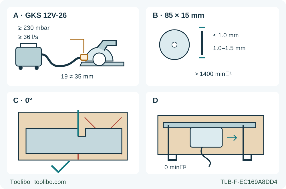
A · Qualify installed extraction
Verify the required performance at the tool connection with the actual adapter, hose and extractor; do not infer compliance from a bare-vacuum rating.
B · Retain the qualified original blade
Match 85 mm diameter, 15 mm bore, body at most 1.0 mm, tooth width 1.0–1.5 mm and permitted speed above 1400 rpm. Uncertain assembly means stop, not improvised fitting.
C · Confirm the square cut reference
With the battery removed, secure zero bevel and less-than-full-tooth depth. Use the left edge of mark 12, with waste right, then verify actual kerf and guide position on scrap.
D · Rehearse while isolated
Clamp and support the sample, keep the underside and runout clear, and check the complete base, guard and hose path before reconnecting the qualified battery.
A locates the required 230 mbar and 36 L/s at the tool connection; a vacuum’s free-air figure is not acceptance. The physical 19 mm adapter and recommended 35 mm nominal hose specification are not interchangeable claims. B is original-assembly qualification, not fitting instructions. C uses the left edge of the correct square mark with waste on the right. D is a conceptual stationary rehearsal with the battery removed: it does not specify running hand placement or commission a rail. Use only the actual designated insulated handle and keep the other hand clear.
The GKS 12V-26 is small enough to tempt an owner to treat it as a self-contained cutting tool. Under the current D1R instructions, however, this sample is admitted only when the original blade, actual battery system and connected dust-extraction installation are all qualified. A hose that physically fits is not proof that the installation meets the required performance at the saw.
This workflow uses the UK GKS 12V-26 product 06016A1001, tool type 3601FA1001 and manual 1 609 92A D1R dated 19 February 2026. The product downloads also show an older manual; that is not a reason to omit the current dust requirements. The separate F10 UK declaration identifies the type but is dated 19 January 2024 despite its 202602 filename. It is identity evidence, not a newer operating procedure.
The outcome is a measured, square, edge-start sample in known clean thin wood, using an already correctly assembled original saw, an already commissioned genuine power system and verified external extraction. This is not a first charging, blade-fitting, guide-rail commissioning or protection-recovery tutorial. If any prerequisite is unresolved, the useful result is a documented hold before cutting.
Qualify the blade without converting the assembly
Match the actual nameplate and controls to the exact instructions. The technical table specifies a 12 V tool with 1400 rpm no-load speed, an 85 mm blade and 15 mm locating bore. The maximum blade-body thickness is 1.0 mm, and tooth width is 1.0–1.5 mm. These dimensions describe different parts of the blade; the 1.0 mm body limit is not a universal kerf value.
Retain the original correctly installed blade and matched flanges and fastening parts. The blade must suit wood, carry the specified EN 847-1:2017 qualification and meet the manual’s stricter fitting statement that its permitted speed is higher than the tool’s no-load speed. A blade merely rated at 1400 rpm does not meet that stricter statement. Do not use abrasive wheels, HSS blades, damaged teeth or an unidentified substitute. No reduction ring, flange conversion or alternative bore is admitted here.
If prior assembly, markings or condition cannot be established, stop for the complete instructions and competent correction. This guide deliberately does not shorten the manufacturer’s removal and fitting procedure into a few bolt directions or turns. The compact blade does not make its exposed edge harmless, even when stationary.
Choose sound loose soft solid wood for the first sample, within the actual verified square-cut capacity and stable enough to clamp. The listed maximum square depth is 26.5 mm, but this is not an instruction to use maximum depth. Do not extend the task to metal, plastics, blind walls or internal plunge cuts. Inspect the material for nails, screws, embedded objects and contamination before setting the saw down on it.
Establish the existing battery system and real isolation
The current manual lists the GBA 12V battery family and GAL 12 / GAX 18 charger families. Use only an actual genuine pack-and-charger combination already qualified under its own complete instructions, with a sound, adequately charged battery. A shared voltage or connector does not establish compatibility with Bosch green tools, Dremel or another brand. This article makes no promise about batteries, chargers or accessories supplied in a particular carton and does not teach charging an unknown pair.
Remove the battery before every adjustment, inspection, accessory check and cleanup. Press the release buttons and withdraw it without force. Keep it physically separate while setting up; a released trigger, lock-off button or extinguished worklight is not isolation. Before later insertion, ensure the switch is off, then push the qualified pack in until it clicks into place.
The charge indicator appears when the trigger is pressed halfway, and the worklight comes on with a light or full trigger press. Those are powered control functions, not ways to prove a tool is isolated. Do not attach a battery merely to illuminate a depth-setting or guard-inspection task. Damaged, modified, leaking or abnormally hot batteries stop the workflow; do not open or repair a pack.
Admit the installed extraction system before arranging a cut
The D1R dust section requires dust-reducing measures, ventilation and suitable breathing protection. This workflow uses connected external extraction throughout. The specified required vacuum pressure is at least 230 mbar, and required flow is at least 36 L/s, measured or verified at the power tool’s dust-extractor connection. The table recommends a 35 mm nominal hose and dust-class M filtration. A vacuum’s free-air maximum, motor wattage or claim of strong suction does not establish these installed values.
The adapter’s physical connection can accept a 19 mm hose. That fit statement and the 35 mm nominal hose recommendation concern different aspects of the installation; neither cancels the other or reduces the at-tool performance requirements. Obtain confirmation for the actual extractor, hose, adapter and connection arrangement under their complete instructions. This article does not invent an adapter stack, a DIY measurement method or an approved vacuum model. If the installation cannot be substantiated, do not make the sample.
With the saw battery removed, verify that adapter 29 is correctly secured to the base with its intended screw 28 and that the connected hose is secure. The specific instruction says this adapter must only be fitted with external extraction connected, and no dust bag may be attached to it. An earlier generic reference to dust boxes or bags does not override that adapter-specific prohibition. Do not leave a disconnected adapter on the saw as if it were a harmless chute.
The documented order is extraction adapter and hose first, then the parallel-guide/guide-rail adapter, using only intended screws. This task starts with that complete assembly already correctly qualified; it does not authorize substituting screws or guessing which accessory variant fits. Confirm the duct is clear and the hose route does not interfere with the guard, guide, clamps, stock or saw travel. If suction falls during work, stop and eliminate the cause before continuing.
Set depth and square angle from the correct references
Keep the battery removed. Check that the lower guard moves freely and closes immediately, with no contact against the blade or other parts at all angles and depths of cut. Check its spring and retracting lever. A dropped saw, bent guard, sticking mechanism or failed return requires correction before operation. Do not tie the guard open, and keep hands out of the chip ejector and beneath the blade.
Loosen depth wing bolt 17. Move the body away from the base for a shallower cut, or toward it for a deeper cut. Read scale 18 at reference mark 31 beside it, then retighten the wing bolt. The actual projection beneath the wood must be less than one full tooth; inspect the real stock relationship rather than trusting a number on the scale. Confirm that the locked position will not move and that the blade clears all supports underneath.
For this sample set zero bevel. Use the actual bevel wing bolts 10 and the upper-edge reference mark 27 on the holder when reading scale 9, then secure all applicable locks. Do not confuse reference 27 with the depth mark or the cutting-line notch. The manual notes that bevel cuts have less depth than the depth-scale value, but this square task does not teach an angled cut.
The 0-degree cut mark 12 is the square reference; mark 11 is for 45 degrees. Use the left edge of the appropriate square cut mark as shown in the instructions, with waste on the right, and verify the real result on a test piece. Do not put the blade centre on the finished boundary and assume the mark compensates for every possible blade.
Clamp the sample and rehearse the complete system
Secure the loose sample to a stable platform. Keep the retained portion supported so the base does not tip as the waste separates, and arrange the offcut so it cannot close the kerf or pull the main piece out of position. Supports near the cut and panel edges must stay clear of the blade path. Do not hold the stock in your free hand, on your leg or above head level.
Use the already matched parallel guide against a sound straight edge, setting its initial width at the outer edge of the base plate as the manual directs, then securing the actual guide fastening. Confirm the intended screws and unobstructed lower-guard movement. The scale is a starting setting; measured sample width is the acceptance evidence. Alternatively, a suitable securely clamped auxiliary straightedge requires its own verified contact-side offset. Do not infer guide-rail readiness from the same accessory’s name: this task does not commission a rail or authorize a bevel cut on one.
Wear eye and hearing protection and appropriate respiratory protection. Keep the area ventilated, maintain the qualified extraction and keep other people away from the cut and dust. Rehearse the whole route with the battery still removed, the blade clear of the wood and the base supported. Check both entry and exit, clamp clearance and whether the hose follows without tugging or becoming trapped.
Hold the tool at its designated insulated handle and keep a firm controlled grip. Position your body to either side of the blade, not in line with it. The actual compact tool has one identified handle; do not invent an auxiliary grip on a guard, ejector, battery or motor cover. Keep any free hand away from the cutting area, underside and waste, never using it to hold the work. If the selected setup cannot be controlled at the proper grip without reaching or interfering with the hose, change the setup before attaching the battery.
Complete the edge-start trial and respond conservatively to an interruption
With the switch off, insert the qualified battery until engaged. Start the connected extractor according to its own instructions. Rest the base securely at the starting edge with the blade clear of the work. Press lock-off 3, then press and hold trigger 4; it cannot be locked ON. Let the blade reach operating speed before entering, then guide the saw forward gently and evenly. Keep the base and guide contact stable rather than forcing a slowing blade or twisting to chase a mark.
Allow the guard to work automatically. Keep fingers away from the ejector, and do not move clamps or catch the offcut while the tool is running. Complete the cut with controlled support, release the trigger and wait for the blade to stop completely. The integrated run-out brake shortens coast-down but does not establish a fixed waiting time or replace the lower guard. Require standstill and guard coverage before setting down, then remove the battery before measurement or inspection.
If binding, loss of support, reduced extraction or another abnormality occurs, release the trigger and hold the saw motionless until complete stop. Do not pull a rotating blade backward or lift it from the work. Isolate before assessing the cause. The indicator has distinct meanings: steady red signals excessive battery temperature, while flashing red indicates blocking. The source describes subsequent responses, but this bounded workflow provides no automatic-restart or recovery recipe. A cleared indicator is not clearance to resume, and an unresolved fault requires the complete instructions and appropriate qualified assistance.
Accept the sample and preserve the verified system
After complete stop, guard closure and battery removal, measure the retained width at both ends and check squareness to the reference edge and through the thickness. Inspect the cut, guide security and actual support through separation. Burning, excessive tearing, changing width, vibration, a shifted setting or a hose snag means the setup has not passed, even if the board separated.
Record the original blade identity, actual pack, extraction-system evidence, stock thickness, depth reference, square mark and measured sample result. Changes to the hose arrangement, blade, guide or geometry require renewed verification of the affected conditions before valuable work. Keep the dust adapter clear; with the battery removed, clean the retracting-guard area with a brush and keep ventilation openings free. Do not introduce a solvent, oil or blade-service recipe from an incomplete maintenance excerpt.
Store the isolated saw with the blade guarded and the battery protected under its own instructions. This completed trial qualifies one exact wood-cutting system. It does not prove that any 12 V battery fits, any hose provides sufficient extraction or any small saw is suitable for every thin material.
Models referenced