
Four conditions for this existing-owner sample
A shows the original diamond-opening blade concept. B separates depth-lever bottom contour, a partial tooth below stock and zero bevel. C shows a larger zero notch and smaller 45° notch. D shows a guide on the right of a conceptual base and a separate bottom-thread oil-level reference.
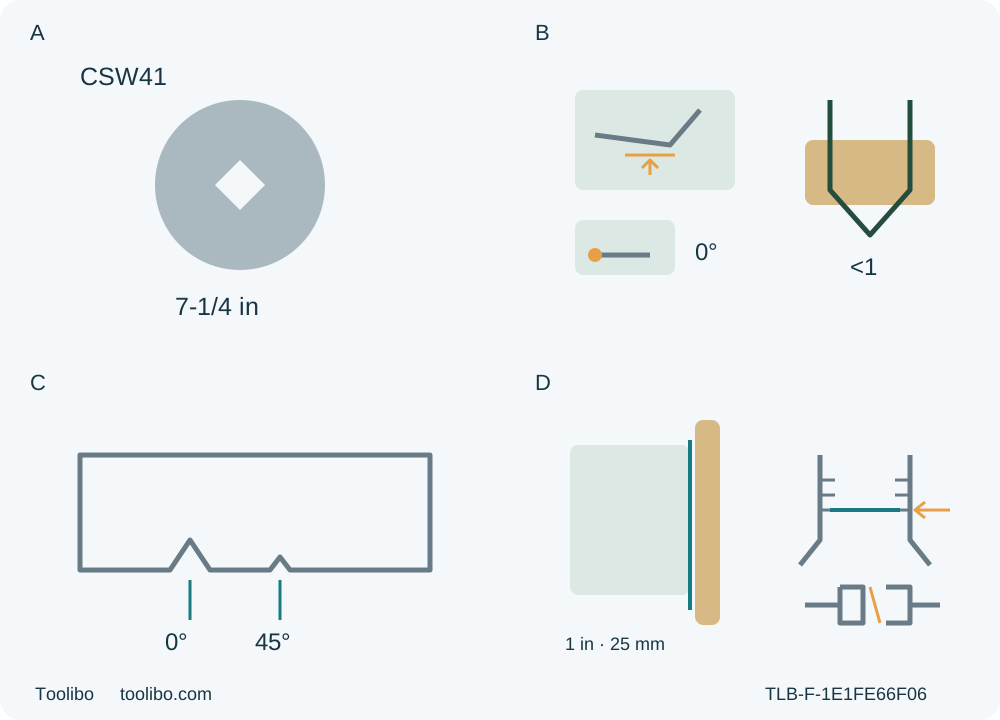
A · Qualify the actual original system
The manual specifies the diamond opening and correctly established Vari-Torque assembly. Unknown original blade, hardware or clutch condition requires qualified correction, not round-hole conversion.
B · Isolate and verify the depth
With the plug disconnected, use the depth lever’s bottom contour and lock it; actual projection must be less than one full tooth while cutting through. The separate front bevel lever holds zero.
C · Recognize the square reference
Use the large zero notch for this sample, not the small 45° notch. A safe scrap trial establishes the real cut/guide relationship; the appearance face is down.
D · Close guide and oil prerequisites
The right foot edge follows the clamped 1 in (25 mm) board guide. Separately, the mandatory exact oil check must be competently completed for this use, with level not below bottom housing threads and the combined plug/lock assembly restored; unknowns mean HOLD.
All symbols are conceptual and not to scale, not assembly or service instructions. A does not resolve the current product 5/8 in discrepancy. B requires an actual through-cut with less than one full tooth, not the later illustration’s full-tooth equality. C is only notch recognition, not a factory offset. D separates the right-foot guide from the mandatory oil-condition evidence: the bottom-thread reference is not permission to fill, drain or run a warm-up, and a safe unplugged maximum-depth support/clearance arrangement must already be established. No panel depicts a running cut.
This is a complete, modest square guided cut for an existing owner of the US Bosch CSW41, not a blade-fitting or oil-service lesson. Match the actual CSW41 body, its nameplate and the supplied 1619X08893 09/13 instructions. The current US product identifies order 060166D011 and body 3601F6D010. A similar rear handle or the words “worm drive” on another saw do not establish that its controls, lubricant or assembly are interchangeable.
Do not begin with an uncertain blade, clutch or oil condition. The original approved diamond-opening blade and original washers/stud must already be correctly established. The mandatory oil-level check must have been competently and correctly completed for this use, not merely at some earlier service. Unknown oil, low level, contamination, overdue first-ten-hour service or uncertain oil-plug/lock-button function means HOLD for qualified Bosch service before any sample.
1. Close the original assembly and lubrication gates
The manual specifies a 7-1/4 in blade with a diamond arbor opening. Its actual assembly drawing agrees. The current product table says 5/8 in; this guide does not turn that discrepancy into round-hole fitting permission. Keep only the actual original, correctly qualified wood-cutting assembly. If the blade identity, approval, condition or fit cannot be established together with the nameplate and matched instructions, stop. No replacement blade number or separate numerical replacement-speed threshold is invented here.
The original combination blade is described for both wood crosscuts and rip cuts. The blade, washers and stud also form the documented Vari-Torque friction clutch. It depends on a correctly established assembly; excessive stud tightening defeats its action. This is not a brake, a guarantee against kickback or a reason to accept dull teeth, poor support or forced feeding. Do not alter the stud, knock out a blade center or adjust the clutch using this article. Slippage, unexplained vibration, damaged or incorrect hardware and uncertain prior fitting require qualified correction.
Page 14 requires the oil level to be checked before using the saw. The specified check is unplugged, with the foot horizontal and the tool set to maximum cutting depth; the combined oil-plug/lock-button assembly is removed with the supplied wrench, the level must not be below the bottom housing threads, and the assembly must be replaced when finished. This paragraph states what must already have been correctly completed; it is not a partial service procedure. At maximum depth the blade projects below the foot: the actual isolated support must keep the tool stable, the foot in the specified position and the blade clear without exposing anyone to the teeth. A flat bench by itself is not proof of that arrangement. If the actual safe setup, access or restored assembly cannot be established under the complete instructions, obtain qualified service rather than improvise.
The manual names WD7LUB or Skil 80111, while the current product lists BL8LB. Their equivalence is not established here. Do not choose a new oil from a similar name. Dirty or thick oil and the manual’s first-ten-hour oil-change requirement must be resolved before operation. Filling, draining, the described one-minute warm-up, brush work and internal service are outside this workflow. A past “serviced” label does not replace today’s mandatory condition check.
2. Qualify the actual power supply and dusty workplace
The current US product lists 120 V, 15 A and 5300 rpm; the manual directs the owner to the actual nameplate. Use only a sound, correctly matched supply, plug and cord. Do not connect an AC-only tool to DC, modify the plug, bypass protection or attempt electrical repairs. A known damaged cord or switch fault is a service hold, not an invitation to reproduce the fault while powered.
Prefer a qualified supply path that does not need an extension. If an extension is necessary and the actual tool is the documented 120 V, 15 A version, the manual’s 12–16 A row gives 14 AWG for 25 ft and 12 AWG for 50 ft. Its 100/150 ft entries and corresponding metric entries are blank: do not extrapolate a longer permitted run. The whole actual cord must be suitable for the location and current, undamaged and routed away from the blade, waste, sharp edges and operator’s feet. Unknown supply capacity or unsuitable extension conditions mean stop for qualified advice.
Work in a dry, well-lit, uncluttered area without flammable liquids, gases or explosive dust atmosphere. Exclude children and bystanders. Use eye protection and appropriate hearing protection, non-slip footwear and suitable approved respiratory protection for the actual dust. Keep clothing, hair and jewelry clear; maintain clean, dry handles and stable footing.
This product explicitly lists no dust collection, no dust blower and no electric motor brake. The manual provides no native hose-connection procedure. Do not invent an adapter, tape a hose to a guard or treat the absence of a port as permission to work in an unsuitable dusty room. The actual ventilation, exposure controls and PPE must be appropriate to the known material and workplace. If the job requires native capture that this qualified system cannot provide, choose another qualified system or do not cut. Ventilation is not a dust-free guarantee.
3. Inspect the isolated tool and select the sample
Release the trigger, wait for actual complete standstill and unplug before inspection or adjustment. Confirm the trigger moves correctly and returns to OFF, and remove the setup wrench from the working mechanism. A switch that fails to start or stop the saw must be repaired; do not continue using it. The supplied wrench has a specific storage orientation and must engage its second retaining detent. Incorrect storage can damage the work. If it cannot be stowed correctly under the manual, resolve that before use. Keep the unused saw hook snapped into its closed position.
Check the lower guard before each use. Using only its lift lever, confirm free movement, immediate closing and no contact with the blade or any other part at all cutting angles and depths. The spring must function correctly; a sluggish, bent or damaged guard, especially after a drop, needs service. Never tie or clamp it open. The guard works automatically during the ordinary edge-entry cut below, and neither hand may obstruct it.
Inspect the accessible original blade and tool for dullness, damage, contamination, loose or incorrect parts, misalignment and binding. Do not remove the blade or use a chemical or compressed-air cleaning recipe from this guide. Uncertain internal condition, pitch that needs blade removal, damaged parts or an unexplained fault is a qualified maintenance matter before cutting.
Choose a modest, dry, known wood sample with the qualified original combination blade. Inspect the complete proposed path and both portions for nails or other foreign material. Avoid warped, wet, green or pressure-treated stock in this first sample, and reject pieces too small for secure support, the full retained-side base path, two-hand control and clamp clearance. No metal, masonry or abrasive-wheel work is included.
4. Establish depth, zero bevel and the right-side guide
With the plug disconnected, loosen the depth lever located between the guard and handle. Hold the foot supported and raise or lower the saw by its handle under the matched instructions. Read the desired cut depth against the bottom contour of the depth lever, not an assumed pointer elsewhere, then tighten the lever and verify the actual result.
The general safety rule requires less than one complete tooth below the wood, while the later operating paragraph says no more than one and its illustration shows a full tooth. Use the stricter actual less-than-full-tooth condition while still cutting through the sample and keeping the blade clear of every support. A scale reading alone does not settle this. If that actual setup cannot be established safely, hold the cut.
For the manual’s 90° check, keep the plug disconnected and first establish a safely supported maximum-depth setup with the projecting blade clear of the support. Loosen the separate front bevel lever, set zero and retighten it, then check the square relationship under the complete matched instructions. This article does not teach calibration or maximum-depth stability-screw adjustment. After the check, restore and lock the sample depth and reverify actual through-cut clearance with less than one full tooth projecting before cutting. A setting that will not hold or a square check that fails needs qualified correction. The 45° stop spring and higher-angle settings are not part of this sample. Product and manual 45° capacity figures differ; no blended capacity is used.
Use the large notch for 0°, not the smaller 45° notch. The notch is an approximate line reference; a safe scrap trial establishes the actual cut and guide relationship. Place the appearance face down as the manual directs, without promising a perfect finish on either face.
For this guided rip, use the manual’s straight 1 in (25 mm) board-guide arrangement, clamped rather than nailed to the sheet. The right side of the saw’s foot runs against that guide. Position it from the actual measured guide-to-cut relationship, keeping the blade kerf on the intended waste side. Do not invent a factory offset or use a dimension from another saw. If no safe trial and actual offset are available, qualify those before making a final-size part.
Secure the retained work and guide; independently support both portions near the cut and their edges, outside the entire blade path. Supports must not allow sagging or trap the waste against the blade. The manual shows support timbers resting on their broad faces rather than an unstable narrow edge. It does not give a universal support spacing or load rating. Verify the actual clamps, guide thickness, base, guard, cord and waste clear each other throughout travel. Make any reach check isolated, beside or safely above the path with the blade covered and no tooth contact—not by pushing it through uncut stock. Failure of any actual support or clearance gate means hold, not hand-support the waste.
5. Make one controlled sample and finish completely
Before connection, confirm the trigger is OFF, adjustments secure, guard free, wrench safely stowed, oil and assembly gates still satisfied, and the actual cord path clear. Take the main handle in one hand and the auxiliary handle in the other, using the insulated gripping surfaces. Stand to either side rather than in the blade line, with balanced footing and both hands away from the cutting area, underside and region behind the blade.
At the ordinary entry, support the front of the foot on the retained work with the blade clear. Squeeze and hold the trigger, allow full speed before contact, and guide forward with light, continuous pressure, keeping the foot supported and its right edge against the straight guide. The lower guard operates automatically. Do not force the saw, steer sideways, change settings in motion or reach for the separating piece. An unstable foot, dragging cord, unusual noise, burning, slippage or loss of control ends the attempt.
For normal completion, finish the cut, release the trigger and maintain control through actual full coast-down. Observe the lower guard covering the blade before placing the saw on a stable clear surface; keep it away from your leg and clothing. There is no electric-brake or fixed stopping-time promise. Unplug before inspecting the sample or touching the setup.
If the blade binds or the cut is interrupted, release the trigger immediately and hold the saw motionless in the material until fully stopped. Do not pull backwards or lift a moving blade out. Safely isolate and have the cause and any trapped-tool condition resolved; this article does not teach an old-kerf restart. If a switch fails to turn the saw off, the manual requires immediate unplugging and no further use until repair—do not keep experimenting with the switch.
6. Accept the result and record what changed
With the tool unplugged, check that the sample is fully separated, the retained width matches the intended measured result at entry and exit, the edge is straight and square, and both faces are acceptable for the next planned task. Look for severe tear-out, burning, unexpected blade marks or signs that the work shifted. A successful-looking edge does not cancel a slipping clutch, abnormal sound, poor guard action or uncertain oil condition.
Accept the setup only when both the work result and tool behavior were normal and all original prerequisites remained satisfied. Record the actual material, thickness, blade identity, depth, guide relationship, supply path and any observation needing qualified service. There is no universal tolerance or load-bearing claim. Requalify changes instead of assuming yesterday’s offset or condition still applies.
Leave the tool unplugged for external inspection and storage, with blade covered, cord protected and access restricted. Keep vents and controls clear without inserting objects into openings or disassembling the tool. Required oil, clutch, brush, bearing or internal guard work remains with complete qualified service; do not postpone it to obtain another sample. The next use begins again with the mandatory oil and guard checks.
Models referenced