
Recognize the isolated CS5 distinctions
A identifies the original round 5/8-inch assembly and disconnected cord. B separates rear depth and front zero-bevel controls with less than a full tooth. C places zero left and 45 degrees right. D shows an isolated upward-travel plan with blade left, retained support and 25 mm clamped board guide right.
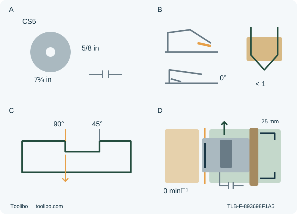
A · Match the original assembly
Original approved 7¼-inch round 5/8-inch wood blade and Vari-Torque hardware/rating must already be qualified; no invented numerical blade threshold, fitting or clutch adjustment.
B · Restore the working depth
Unplug and safely support the maximum-depth square check, then restore and lock through-cut depth with less than a full tooth; rear depth and front bevel are separate.
C · Use the left square notch
The left 90°/zero reference is for this square cut; right 45–56° is excluded. Verify the real line on equally safe scrap.
D · Qualify the entire guide path
If using the documented 1-inch/25 mm board guide, clamp it securely and use the right foot edge, with actual offset, tool/clamp clearance and independently supported free waste; no live rehearsal.
Original isolated concepts are not to scale, a fitting procedure or a live cutting pose. B requires a safe maximum-depth square check followed by restoration of actual partial-tooth through-cut depth. C is approximate, not a calibrated offset. D illustrates only the documented right-foot board-guide relationship; actual guide height, clamp clearance, broad retained support, independent free waste and full reach must qualify. No dust connection is depicted or inferred; actual environmental suitability remains a pre-cut gate. The 25 mm label identifies the source-stated board-guide dimension, not its drawn plan-view width or a universal clearance.
Decide whether this particular saw belongs in the job
This is an existing-owner workflow for the US Bosch CS5, matched to the actual tool and its 1619P06013, 09/12 operating instructions. The current official product page links that manual. Its URL ends in 0601672074, while the displayed part number is 0601672075: compare the actual identification plate and manufacturer documentation rather than treating the numbers as interchangeable aliases. The complete outcome is one modest, supported square cut in known loose wood, followed by an unplugged assessment of the pieces and setup.
The CS5 is a blade-left body with its own controls and references. It is not a CS10 with its diagram mirrored, nor does its layout establish the CSW41’s drive or oil requirements. This guide assumes the original manufacturer-approved wood blade, round-arbor mounting hardware and Vari-Torque assembly are already correctly qualified. It teaches no blade, washer, stud or clutch adjustment.
An equally important limit comes before layout: the current product explicitly lists no dust collection, no blower and no electric motor brake. The matched manual does not establish a native extraction port or an adapter installation. Do not fit a CS10 dust chute, improvise a hose connection or regard an external vacuum nearby as demonstrated source capture. If the material, workplace or applicable work requirements demand native capture that cannot be provided by this documented system, hold the job and choose another qualified system. The absence of a port is not permission to ignore exposure.
Qualify the original blade, tool and electrical supply
The manual specifies a 7¼-inch blade and a round 5/8-inch arbor opening. The actual installed blade must already be approved for this CS5, correctly rated and appropriate for the known wood. The original combination wood blade is described for crosscuts and ripping; do not assume any unidentified replacement has that approval. The current product’s 6200 rpm is a motor specification. This manual does not supply a separate numerical blade-rating rule to quote, so this article does not invent one from that figure. Unknown blade identity, approval or rating is a pre-cut hold.
With the plug disconnected, inspect the accessible original blade, washers, stud, guards, base, handles and housing. Dullness, damaged teeth, loose or incorrect hardware, unexplained rubbing, binding, misalignment or abnormal vibration requires qualified correction. The Vari-Torque system depends on the correct existing blade-and-washer condition and setting; a slipping or uncertain assembly is not adjusted by trial here. Do not transplant another saw’s tightening direction, extra turn or service recipe.
The lever labeled “lock lever” in the tool diagram is used to lock the shaft during the manual’s assembly procedure. It is not a trigger lock-off. Ordinary starting below uses the actual trigger; no additional start-button sequence is invented.
The US product identifies 120 V and 15 A, while the manual directs the owner to the actual nameplate. Match the real tool, supply, intact cord, plug and outlet. Do not modify a plug or use an AC-only tool on DC. If an extension is necessary, follow the complete selection instructions and actual conditions. For a matching 120 V tool in the 12–16 A row, the manual lists 14 AWG at 25 ft and 12 AWG at 50 ft; the 100 and 150 ft entries are blank. Do not extrapolate longer runs or transfer those figures to a different supply. Uncertain electrical arrangements need a competent solution, not a repeated reset or repair attempt.
Make the dust and work-area decision substantive
Use known dry wood with no unidentified coating, chemical contamination, embedded nails or other foreign material in the whole proposed route. The manual calls for special attention with green, wet and treated timber; those materials are outside this modest sample. Metal, masonry and abrasive-wheel work are also excluded. Inspect before marking, not after encountering a fastener.
Choose a dry, well-lit area with stable footing, no explosive atmosphere from flammable liquids, gases or dust, and no bystanders exposed to the cut or airborne waste. Arrange actual ventilation and task-appropriate approved respiratory protection for the material, as well as eye and appropriate hearing protection. Avoid directing ejected dust toward yourself or another person. An open door or working outdoors is not, by itself, proof that the exposure is controlled. Consider the actual quantity of dust, nearby people and whether the location can be kept clean without spreading it. If you cannot establish a suitable working environment under the material and safety instructions, do not start.
Keep loose clothing, hair and jewelry clear. Route the cord so it cannot be cut, snag a support, pull the saw or cross the waste path. Do not ask the spare hand to manage it during the cut: both hands are required on the saw. This route deliberately claims no source-extraction performance, dust-flow threshold or improvised enclosure.
Inspect the isolated guard and controls
Before every setup, release the trigger, wait for complete standstill and unplug. Check that the trigger actuates freely and returns to OFF when released. A switch that fails to start or stop is not a diagnostic exercise: the manual requires disconnection and repair before further use. Keep control of the tool and keep clear of the blade; do not repeat a powered test of a suspected fault. Remove adjustment keys and other setup items before reconnecting.
Check the lower guard before each use. Using its intended lift lever while safely isolated, confirm free movement and immediate closure without touching the blade or other parts at all angles and depths of cut. Check the spring, including after a drop or impact. A bent, obstructed or slow guard needs service before use; do not tie it open, straighten it here or dismantle it to clean the spring. Ordinary cutting uses automatic guard movement. Neither gripping hand may interfere with that movement, and no hand holds the guard open during the sample.
Both the rear housing depth lever and the front bevel lever must lock securely. A loose setting can change during the cut. Do not compensate for a lever that will not hold by gripping harder or feeding more slowly.
Check square, then restore the actual working depth
The manual’s 90-degree check starts at maximum depth. Perform it only unplugged with the tool stably supported and the exposed blade safely clear. Set the foot to maximum depth, release the front bevel lever, set zero on the quadrant, retighten, then check the blade-to-foot relationship with a square. The alignment screw is a service boundary in this workflow: a failed check requires qualified correction, not an abbreviated adjustment lesson.
Afterward, restore the actual sample depth. Release the depth lever in the housing, hold the foot down on a safe support and raise or lower the body by the handle as the matched instructions describe. Tighten the lever and verify the setting. The blade must cut through the stock while leaving less than a full tooth below it and clearing all clamps and supports. This stricter general safety limit governs the sample despite the later “not more than one tooth” wording and full-tooth illustration. The maximum-depth square check is never permission to leave excessive blade exposed.
Keep the bevel at zero. The current product’s 45-degree capacity differs from the manual’s, and neither number authorizes an angled cut here. Do not reconcile them into a new specification. For this job, actual square geometry, through-cut and partial-tooth clearance are the relevant checks.
Lay out the line and, if used, the exact board guide
Mark the wanted piece and a square line from a verified straight reference edge. The left side of the foot notch is the CS5’s 90-degree reference; the right side belongs to 45–56-degree cuts excluded here. Put the appearance face down as the manual instructs. Check the actual cutting line on equally safe scrap because blade thickness and the approximate notch can affect where the edge ends up. This is not a guaranteed finish on both faces.
For a guided square rip rather than a crosscut, the manual documents a straight 1-inch/25 mm board guide clamped to the sheet, with the right side of the foot against it. Use only this actual orientation, not a mirrored CS10 arrangement. The guide must be straight, secure and placed using the actual verified blade-to-contact relationship so the kerf falls on the waste side. Its height, clamps and the tool’s full travel must clear the motor, handles, guard and cord. If that real geometry is not available, do not improvise a thinner guide or claim a universal offset. Choose another fully qualified setup or hold the cut. A guide is optional for an ordinary modest crosscut; it does not replace support or a safe hand path.
Clamp the retained work securely and preserve continuous support beneath the retained part of the foot. Independently support the waste so it cannot sag, twist, fall into the blade or close the kerf, while leaving it free to separate. Do not clamp across the line in a way that traps the blade. For large stock, the manual calls for support near the cut and edges on both sides; supporting timbers rest on their broad faces, not unstable narrow edges. The blade must clear them. No hand, knee or helper catches the offcut.
Choose a modest piece and complete route that can be reached without leaning, changing grip or moving clamps while running. Rehearse reach and cord clearance while unplugged beside or safely above the route, with the blade guarded and no tooth contact. Never push the stationary blade into uncut stock or force the guard for a “dry cut.” Missing support, inadequate grip access or an unclear exit means hold before connecting.
Cut with both hands and let the blade actually stop
Confirm OFF, then connect to the qualified supply. Grip the main handle and auxiliary handle firmly using the insulated gripping surfaces. Keep the body to either side of the blade line, hands out of the cutting area and underside, and never place a hand behind the saw. Ensure neither hand obstructs the lower guard. The blade-left view does not justify a one-handed cut.
Place the front foot on the supported work with the blade clear. Squeeze and hold the trigger, allow full speed, then advance forward with light, continuous pressure. Keep the foot flat and, where the qualified guide is used, maintain its intended right-foot contact without sideways forcing. Do not twist the saw to recover a missed line or force it through slowing, burning or abnormal resistance.
For binding or interruption, immediately release the trigger and hold the saw motionless until the blade stops. Never pull it backward or lift it from a trapped kerf while moving. Unplug before investigation; unstable stock or a trapped tool may require qualified help. This article does not teach old-kerf restart.
After normal completion, release the trigger and wait for actual complete standstill. During coast-down, keep the saw from brushing your leg, side or clothing, which could retract the guard. Confirm the blade is covered before safely setting down, then unplug for measurement. There is no electric brake or promised stopping interval to substitute for observation.
Close the sample and maintenance boundary
Measure the wanted piece against its marked datum; check square, edge straightness, both faces and separation damage. Look for burning, torn fibers, unexpected kerf movement or signs that a support shifted. Accept only the result the actual task requires, without invented tolerance or load claims. A separated but damaged or inaccurate piece is not automatically a pass. Record the actual tool/manual identity, blade qualification, supply, environmental controls, depth, support/guide arrangement and measured result.
Correct planning or material issues while isolated; tool faults require qualified service before another sound-tool sample. Keep the unplugged saw dry and protected, and accessible vents clear under the complete care instructions. The manual’s brush, lubrication, bearing, blade-cleaning and sharpening passages are not an oil check or repair recipe here. No internal disassembly, solvent, compressed-air, clutch or blade-service procedure is supplied. That boundary preserves a complete owner cut without pretending the CS5 has another model’s maintenance or dust system.
Models referenced