
Recognize the qualified isolated system
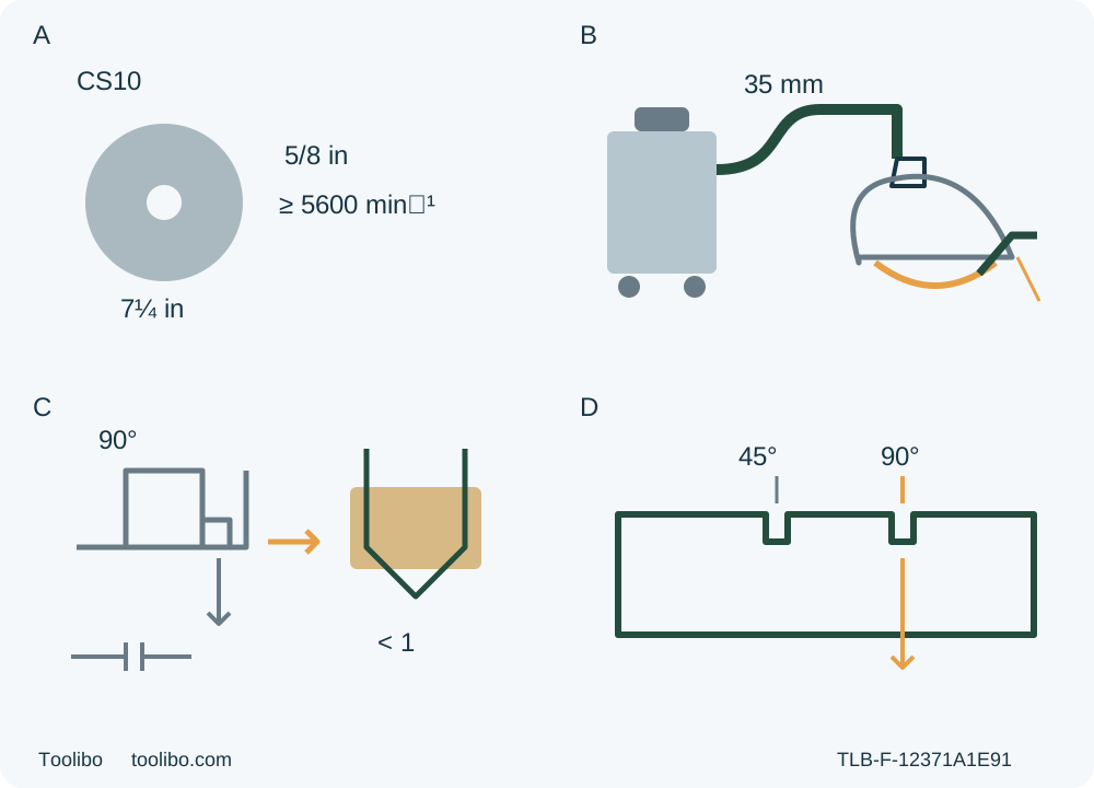
A shows a round 5/8-inch blade rated at least 5600 rpm. B connects a 35 mm hose to the conceptual complete port and marks the required guard lever. C separates the maximum-depth square check from the final partial-tooth sample setting. D identifies the right 90-degree notch.
A · Verify the original assembly
Actual approved round 5/8-inch wood blade rated at least 5600 rpm and original correctly qualified Vari-Torque hardware; unknown condition means HOLD.
B · Require the whole dust system
With saw unplugged and extractor isolated, verify the existing complete CSDCHUTE, required replacement guard lever and documented 35 mm connection; activate suitable extraction before cutting.
C · Restore the sample depth
Perform the manual square check at maximum depth only in a safe unplugged setup, then restore and lock actual through-cut depth with less than a full tooth and clear supports.
D · Use the right square reference
The right notch is 90°; the left angled reference is not used. Verify the actual line on equally safe scrap, then cut with both handles and full-speed entry.
Original isolated concepts are not scale drawings, retrofit steps or a running pose. A does not authorize blade or clutch work. B requires the complete already-installed CSDCHUTE arrangement, including its correct replacement guard lever, and an appropriate active extractor during cutting. C requires safe unplugged support and blade clearance at maximum depth, then restoration and verification of actual through-cut depth with less than a full tooth. D is an approximate reference, not a factory offset; no angled cut is taught.
Start with the actual 07/19 system, not just the CS10 name
This workflow ends with one supported square crosscut in known loose wood and an unplugged assessment of the separated pieces. It is for an existing US Bosch CS10 whose physical controls, original approved blade assembly and supplied instructions match 2610051973, 07/19. It is not a new-tool commissioning or accessory-installation guide. The current US product page links the older 09/12 manual; the manufacturer also hosts the selected 07/19 document, which contains additional blade and dust-collection requirements. Do not call 07/19 the current product-linked revision, mix the two procedures or assume that a familiar model name establishes applicability. An uncertain actual match requires Bosch clarification before work.
This particular route also requires the complete, correctly installed CSDCHUTE dust arrangement, including its required replacement lower-guard lift lever, and a suitable active extractor. It is not enough to attach a hose to an unidentified opening. If the existing arrangement, lever, fastening, clearance or complete manufacturer instructions cannot be established, stop here. This article does not teach a partial retrofit. The product page’s “Dust Collection NO” field does not make the optional documented arrangement factory-included, and the blower is not extraction.
Qualify the original assembly and the supply
The selected manual identifies a 7¼-inch blade with a round 5/8-inch arbor opening. Its speed rating must be at least 5600 rpm. The table states 0.1 inch (2.6 mm) tooth thickness, with a footnote giving a minimum of 0.07 inch (1.8 mm), and a maximum plate thickness of 0.07 inch (1.8 mm). These are checks against the actual approved original blade and complete instructions, not a replacement shopping shortcut or permission to round measurements. The blade must be appropriate for the actual wood, sharp, clean and undamaged; the original flush washers, bolt and Vari-Torque assembly must already be correctly qualified. Unknown, loose, damaged or incorrect hardware, unexplained rubbing or suspected misalignment means qualified correction, not a trial cut.
No blade removal, bolt direction, tightening torque or clutch adjustment is taught here. In particular, do not transfer the CSW41 diamond-arbor system, clockwise-removal instruction or pre-use oil routine to this conventional CS10. A common brand does not establish shared mechanisms.
Match the actual nameplate and supply. The US product identifies a 120 V, 15 A tool, but the actual cord, plug, outlet and supply still have to be correct, intact and suitable. Do not modify plugs or use an AC-only tool on DC. If an extension is necessary, use the complete manual’s selection method and actual conditions: its 120 V, 12–16 A row lists 14 AWG at 25 ft and 12 AWG at 50 ft. The 100 and 150 ft entries are blank, not permission to extrapolate. An uncertain circuit or extension requires a competent supply solution, not a reset or electrical repair experiment.
Prepare a dry, clear work area and active dust control
Use known dry wood with a clear proposed cut route, free of nails and other foreign material. Do not proceed in wet conditions or an explosive atmosphere containing flammable liquids, gases or dust. Keep bystanders outside the work area and provide stable footing, good light and ventilation. Wear eye protection and the appropriate hearing and respiratory protection for the actual task and dust; extraction does not remove every exposure. Tie back hair, secure clothing and remove jewelry that could reach moving parts.
For hose connection checks, switch the tool off, wait for complete standstill and unplug it; isolate the extractor under its own instructions. Verify the whole previously installed CSDCHUTE system, including the correct replacement guard lever. The manual describes a typical rubber-like 35 mm hose nozzle, not universal compatibility with any hose carrying that number. Actual tool-side and extractor instructions must establish the connection and dust suitability. Especially harmful dry dust or carcinogenic dust requires the special extractor stated in the manual. Do not import a Bosch cordless model’s pressure or flow thresholds into this document.
The hose must remain connected without pulling the tool, entering the cut or interfering with the guard throughout the actual movement. Route the cord separately so it cannot be cut, snag, pull across the operator or fall into the waste path. Activate and check the qualified extractor under its own instructions before cutting; a connected but inactive hose is not the required dust control. If the actual setting cannot provide suitable collection and ventilation, move the task to a qualified arrangement or hold it.
Check the isolated saw before setting the sample
With the plug visibly disconnected, inspect the cord, plug, housing, handles, base, controls and accessible hardware. Check that the trigger operates freely and returns to OFF when released. A faulty switch is a service condition, not a reason to reproduce the fault under power. Remove adjustment keys and other setup items before reconnection.
Check the lower guard before each use. It must move freely, close instantly and not contact the blade or another part at all angles and depths of cut. Check its spring operation and investigate a slow, damaged or obstructed guard through qualified service. Never clamp or tie it open. A drop or impact requires renewed condition assessment; do not infer a bent guard can be straightened in this workflow. For the ordinary edge-entry cut below, the guard operates automatically; no hand is used to hold it open.
The rear depth lever and front bevel lever are different controls. Set depth while unplugged: release the depth lever, keep the foot supported, raise or lower the body as the actual mechanism requires and secure the lever. Detents marked for standard lumber are not measurements of your panel or evidence of safe projection. The actual blade must cut through the stock while exposing less than one full tooth below it, with clearance from every support and clamp. This stricter general safety condition governs this sample even where later wording or a diagram refers to a full tooth. If through-cut and partial-tooth clearance cannot both be met, stop rather than average the instructions.
The manual’s 90-degree check starts at maximum depth. Perform it only unplugged, on a stable setup that safely supports the tool and keeps the exposed blade clear. Release the front bevel lever, set zero, retighten and check the blade-to-foot square relationship as the complete instructions describe. Do not adjust the alignment screw here. If the check fails, obtain qualified correction. After this maximum-depth check, restore and lock the actual sample depth and reverify through-cut, less-than-full-tooth projection and underside clearance. Never carry maximum depth straight into the sample merely because the square check passed.
Build the complete crosscut path
Choose a modest board or panel whose entire cut can be reached without leaning, changing grip or relocating supports while running. The original combination wood blade may serve crosscutting when it is approved and in suitable condition for this material. Mark a square line from a verified reference edge, identify the wanted piece and place the appearance face down as the manual instructs. This is not a guarantee of an undamaged second face.
Clamp the retained work securely. Independently support the portion that will separate so it cannot sag, twist, fall onto the blade or close the kerf; do not clamp across the cut in a way that traps the blade. Supports belong near the cut and the outer edges as appropriate to the actual stock, with broad bearing surfaces and a clear blade path. The retained portion must continue to support the saw’s foot throughout entry, travel and exit. Do not use a hand or knee to hold the stock or catch the waste. Unknown support capacity or an unstable narrow remainder means hold, not an invented minimum overhang.
The right side of the notch is the CS10’s 90-degree reference; the left side belongs to angled settings excluded here. Verify the real line on equally safe scrap before a dimension-critical cut. The notch is approximate, not a calibrated offset or proof that the kerf is on the waste side. Do not transfer a mirrored guide or base layout from another saw. Rehearse reach and cord/hose clearances while unplugged, beside or safely above the proposed route, with the blade guarded and without tooth contact or forcing the guard. If a safe complete route cannot be established, do not start.
Make the normal cut, then assess it unplugged
Confirm OFF before connecting to the qualified supply. With the extractor operating, grasp the main handle and auxiliary handle firmly, using the insulated gripping surfaces. Keep the body to either side of the blade line, not directly behind it. Keep hands away from the cutting area, behind the saw and underneath the work; neither hand leaves its designated grip to move waste, supports, cord or hose. Ensure neither hand interferes with the free movement of the lower guard.
Place the front of the foot flat on the supported work with the blade clear. Pull and hold the trigger, let the blade reach full speed, then feed forward lightly and continuously along the intended line. Do not force the saw or twist it to correct a wandering line. Maintain full control and stable base support through the planned clear exit. Unusual vibration, noise, resistance, smoke, loss of support or a changing hose/cord path is a reason to stop, not to push through.
For binding or any interruption, release the trigger immediately and hold the saw motionless until the blade stops. Do not pull a moving blade backward or lift it from a trapped kerf. Unplug before investigating; an unsafe trapped-tool or workholding condition requires qualified help. This guide does not teach restarting an old kerf.
After normal completion, release the trigger, wait for actual complete standstill and confirm the lower guard covers the blade before setting the saw down safely. During coast-down, do not let the saw brush against your leg, side or clothing. Do not use an assumed brake time or the blower as a stopping indicator. Unplug before touching the cut, changing settings or inspecting anything.
Check the wanted piece against the marked length and a square, inspect the edge and both faces, and confirm that separation did not cause splitting, burning, an unsupported breakout or a closing kerf. Record what the sample actually demonstrates. An inaccurate or damaged piece is not accepted merely because it separated; correct the cause while isolated or seek qualified service before another properly supported sample. No project load rating or installation approval follows from this test.
Leave a usable record, not an improvised repair
Record the actual manual revision, original blade identity and condition, extraction configuration, supply arrangement, sample depth and measured result. Store the unplugged saw dry and protected. Keep accessible exterior surfaces and ventilation openings clean using the complete care instructions; this article supplies no solvent, compressed-air, internal-cleaning or blade-service recipe.
The manual’s lubrication and brush/bearing service provisions are not a user oil-check routine. Qualified maintenance must address them, including the stated brush inspection interval and regreasing at brush replacement. Noisy bearings or any uncertain switch, guard, cord, clutch or blade condition stays out of use pending correction. The successful outcome is one documented, accepted cut with the complete system still qualified—not permission to ignore the next pre-use inspection.
Models referenced