
Six blanks and a complementary pair
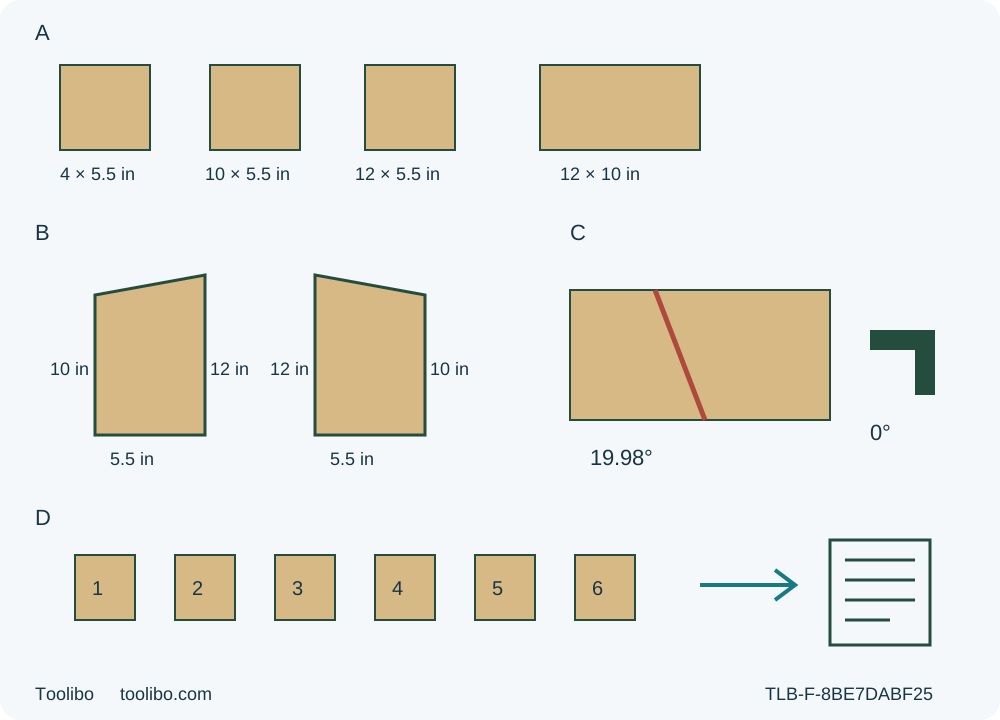
A inventories floor 4 by 5.5, front 10 by 5.5, back 12 by 5.5 and roof 12 by actual 10 inches. B shows two side shapes with 10 and 12 inch edges across 5.5 inches. C keeps blade bevel at zero while the cutting line slopes in the board plane. D shows six labelled pieces handed onward, not an assembled box.
A · Accept actual stock and design
Record all six source dimensions and actual thickness, not nominal lumber names. Stop before cutting if local suitability or the actual roof arrangement remains unresolved.
B · Measure the complementary pair
Across 5.5 in, the side edges are 10 and 12 in. One shared diagonal creates two mating slopes; account for its kerf and mark the second square boundary from the new real edge.
C · Keep the blade square
The approximately 19.98° slope is in the board plane, not a blade-bevel setting. Every cut still needs independently verified long-stock clamping, full shoe support, guard clearance and freely separating supported waste.
D · Hand off a measured kit
Label floor, front, back, two sides and roof with dimensions and orientation. Keep all uncompleted assembly, opening, drainage, finish and installation tasks explicit; these blanks are not a usable nestbox.
The shapes are conceptual and not to scale. All dimensions are inches and are source dimensions, not a tolerance or fixture rating. B is a separated conceptual pair: the real diagonal kerf must be included and each second-side dimension remeasured from the actual edge. C does not depict an operating pose or certify support; the saw stays square while the line changes in the board plane. The actual 10 in roof does not guarantee 2 in side overhang. Local design acceptance precedes cutting, and drilling, drainage, assembly, weather qualification and monitoring remain uncompleted.
A useful saw-stage result is not necessarily an assembled object. This workflow produces six measured, labelled wooden blanks for a specifically accepted NABS 2020 nestbox plan, together with a clear list of work that remains. It does not produce a finished nestbox, demonstrate wildlife suitability or authorize installation. Its distinctive cutting problem is a complementary pair of sloping sides made from long stock, without trimming a loose wedge or recutting the small floor.
Accept the design before buying or cutting wood
Use the complete NABS plan dated January 24, 2020 and its January 2018 nestbox recommendations. The current plan listing identifies the Eastern/Western bluebird design. Regional species, climate, predators and monitoring arrangements matter: an experienced local bluebird adviser and a qualified builder must accept the exact proposed design and assembly before this cut-kit is selected. Do not treat a plan download as universal habitat approval. NABS explicitly says it no longer approves specific designs.
There is a real roof qualification to resolve first. The plan drawing specifies a 12 × 10 in roof and describes approximate side overhang, whereas the recommendations call for 2 in on each side. If two 3/4 in side panels surround a 5-1/2 in front, the outside width is 7 in; a centered actual 10 in roof then leaves only 1-1/2 in per side. That calculation is an assembly inference, not a correction to the plan. Obtain explicit local design acceptance of the actual roof arrangement and weather implications. If a revised roof or box design is required, stop this source-dimension workflow and use a separately qualified complete plan; do not quietly enlarge a part and continue claiming an unchanged kit.
Agree who will complete and inspect the door, entrance, ventilation, drainage, climbing surface, finish if needed, mounting, predator protection and regular monitoring. Those are uncompleted handoff requirements, not optional details to forget after cutting. If the intended builder or monitoring arrangement is unknown, postpone making the kit.
Specify actual stock and the six accepted blanks
This bounded version uses sound, untreated, nail-free solid wood qualified for the installed wood blade and accepted local design. Measure 3/4 in actual thickness and 5-1/2 in actual width for the narrow stock. Use the plan’s 6 ft stock option, not a nominal 4 ft board assumed to yield every piece without saw loss. The roof needs a separate sufficiently long board with actual 10 in width and the accepted thickness. A nominal 1 × 10 may measure only 9-1/4 in wide; its name is not dimensional acceptance. Do not introduce glued boards, fiber-cement, plastic or metal roof alternatives into this wood-only workflow.
Prepare a labelled inventory before marking:
- One floor blank: 4 × 5-1/2 in, with its corners still intact.
- One front blank: 10 × 5-1/2 in, without an entrance hole or climbing grooves.
- One back blank: 12 × 5-1/2 in.
- Two side blanks: each 5-1/2 in wide, with one 10 in and one 12 in longitudinal edge and a sloping top.
- One roof blank: 12 × 10 in actual dimensions.
Record actual thickness, the selected inside/outside faces and the builder’s agreed dimensional tolerances. The source does not supply a universal saw-cut tolerance. A kit that needs unknown assembly compensation is not accepted merely because all six pieces exist. Reject twisted, split, decayed or contaminated stock; inspect every proposed cutting route for nails and other foreign material.
Qualify the saw and every fixture, including the floor
Use an already qualified US Makita 5007MG under instructions 884671-946, with its original correctly fitted approved wood blade, sound supply and complete owner prerequisites. This is not a blade-fitting or electrical setup lesson. Wear appropriate eye, hearing and dust protection and control dust under the actual equipment instructions. Keep bystanders away and secure footing, lighting and working height.
With the plug removed, check the lower guard using its retracting lever. It must move freely, close immediately and avoid the blade and other parts at all angles and depths of cut; the lever must not foul the housing. A damaged or unreliable guard, spring, cord, switch or assembly stops the task for qualified correction. Set and lock the blade square to the base. Use the conservative less-than-one-full-tooth projection below the actual material, lock the depth, and verify that supports cannot enter the blade path. No blade tilt is used for the sloping side tops.
Each cut needs its own physical layout. Secure the long retained stock to a stable support; orient it so the broad portion of the saw base rides on that supported retained stock, not on the piece being detached. Independently support the departing piece outside the blade path so it can separate without dropping, rotating into the blade or closing the kerf. Do not clamp across the intended kerf or use a hand as an offcut support. The guide, clamp heads, housing, guard, both handles and cord need clearance through entry, travel and exit.
The 4 in floor is the decisive fixture gate. It is detached once from the end of long stock; it is never hand-held or subsequently trimmed as a loose small piece. With the saw unplugged and the blade guarded and clear of wood, inspect the actual entry/middle/exit reach and support beside or safely above the path. Do not push projected teeth into an uncut board or force the guard open to rehearse. If full stable shoe support, two-hand control, clamping and independent floor support cannot all be achieved, stop the whole kit or obtain qualified cutting help. The length calculations below do not certify a fixture.
Establish the reference and account for the diagonal kerf
Qualify a straight long reference edge and one square starting end while the stock is still long enough to support safely. Reserve the measured loss from any initial end squaring. Establish the actual straightedge-to-cut relationship on suitable supported scrap with the same blade, square setting and guide-contact side. Do not borrow a factory offset or the offset for the opposite side of the base. At every finished blank boundary, including the first shared diagonal, place the measured kerf on the long-remainder side of the marked finished edge, not inside the blank being detached. Recalibrate the actual guide relationship for the diagonal layout; do not assume its longitudinal kerf allowance equals the perpendicular kerf width.
The side tops rise 2 in across 5-1/2 in, so their in-plane angle from a square crosscut is arctan(2/5.5), approximately 19.98°. The drawing’s approximately 70° relationship is complementary; it is not a 70° blade-bevel setting. Keep the blade at 0° bevel and mark the two endpoints directly. The actual diagonal guide must clear the tool and provide uninterrupted support; an angle on paper is insufficient.
Let k be the measured kerf width perpendicular to the cut, not blade-plate thickness. A diagonal cut consumes q = k / cos(19.98°) along the board. The paired sides consume 22 + q in between their outside square boundaries. The floor, pair, front and back therefore require 48 + 4k + q in, plus the initial squaring reserve. For an expressly hypothetical k = 1/8 in, that is about 48.633 in, leaving about 23.367 in from a measured 72 in board before the initial reserve. A 48 in layout cannot deliver these dimensions with zero allowance. These numbers prove bookkeeping only, not a minimum safe retained length or support span.
Cut the pieces from the long remainder
Start with the floor. Measure its 4 in finished length from the verified starting end and put the measured kerf on the remaining-stock side of that finished boundary. Rebuild the qualified floor fixture and guide; the long remainder supports the broad base. Do not try to correct an undersized floor with another cut.
Next mark the first side from the new actual end: one longitudinal edge is 10 in and the other is 12 in. Join those points for the top cut. Cut the shared diagonal with the blade still square. The detached piece is the first side; the new sloping end on the long remainder will become the top of the second side. This arrangement avoids cutting a small triangular wedge from an already short side.
Measure the second side from that actual sloping edge, not from the old pencil line across the vanished kerf. Its short and long edges must be 10 and 12 in respectively; their endpoints should define one square closing line. Verify both before cutting. If they do not agree because the first angle or stock reference is wrong, hold the pair rather than force a corrective loose-piece trim. The second closing cut detaches the complementary side while the remaining long stock again carries the broad base.
From each subsequent actual finished end, mark and detach the 10 in front and then the 12 in back. Rebuild clamping, guide contact and independent waste support after every cut; never slide a live saw or reposition wood around it. Make the roof’s 12 in length cut from sufficiently long actual 10 in wide stock under the same physical gates. A prefinished roof is acceptable only if its actual dimensions and material have independently passed the agreed design requirements; it is not evidence that an undersized nominal board works.
Before every reconnection, with the saw unplugged, check that the trigger actuates properly and returns to OFF when released, remove any setup key and confirm the switch is OFF before plugging in. A failed switch check stops the task; do not energize a suspected fault. For every normal cut, hold the insulated gripping surfaces of the front grip and rear handle, keep the body out of the blade line, and rest the front base flat on the supported retained stock with the blade clear of the material. Pull the trigger, let the blade reach full speed, and feed steadily without forcing or twisting. Let the lower guard operate automatically. At normal completion release the trigger, wait for complete standstill and guard coverage, then set the saw down and unplug before measuring or rearranging anything. If binding or interruption occurs, release the trigger and hold the saw motionless in the work until the blade stops; never pull a moving blade backward. Isolate and resolve the cause, not by steering harder or restarting a trapped blade.
Accept and hand off the complete kit
After each isolated cut, check length on both longitudinal edges, straightness, square blade-to-face result and damage. Inspect the two sides together as complementary parts: matching widths, 10/12 in edge pairs, matching top slopes and square bottoms. Keep fingers away from sharp splinters; cracked, severely torn, undersized or geometrically inconsistent pieces do not pass. Do not conceal a failed cut by relabelling it as assembly allowance.
The final handoff contains six labelled blanks, actual measurements and thickness, face/orientation marks, the exact accepted plan and local design decision, and a written unfinished-work checklist. Floor corners remain unmodified; no entrance, vents, pivot or drainage holes, shallow climbing kerfs, finish or joints have been made here. A qualified builder must separately establish those operations, fit and retain the opening panel, check weather protection and arrange safe installation and monitoring. Until that separate work is completed and accepted, these are only measured wooden blanks—not a usable, approved or certified nestbox.
Models referenced