
Face geometry is not blade tilt
Hypothetical top view of a 90 mm wide board with 600 mm long point, 510 mm short point and 45-degree end, separate zero-bevel section and arithmetic acceptance.
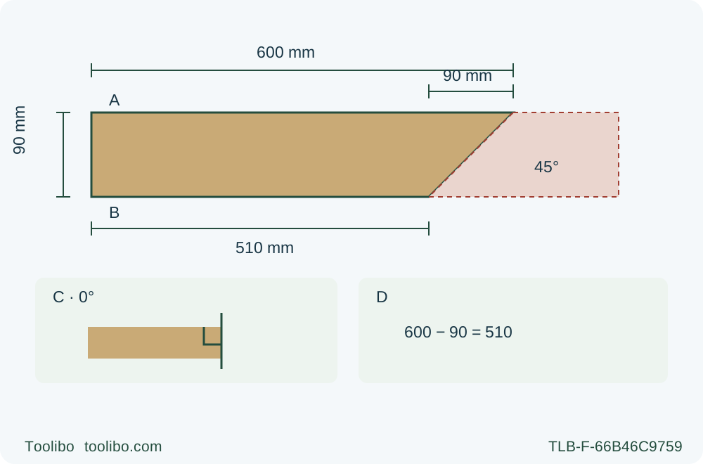
A · Long-point datum
In this illustrative face view, measure the wanted long point 600 mm from the existing square datum along the chosen long edge. This is a hypothetical layout, not a required project size.
B · Short point and waste
For the illustrated 90 mm actual width and 45-degree face diagonal, the short point is 510 mm. Keep the kerf on the waste side; thickness is not this face-layout offset.
C · Blade remains square
The separate end-view concept shows zero blade bevel and a square-through-thickness edge. A 45-degree face line does not call for tilting the saw to 45 degrees.
D · Accept both dimensions
Check the hypothetical arithmetic 600 − 90 = 510, then measure actual long/short points, face angle, cut-edge squareness and finish from the same datum after stopping and unplugging.
A/B are an illustrative top view, not an 18 mm thickness section: actual width controls the 45-degree point difference. Shaded dashed material is waste, with kerf placed on its side. C is a separate conceptual square-through-thickness section. Supports, clamps, cord and the running saw are deliberately not located by this geometry diagram; the complete diagonal-travel plan is required before cutting.
An angled end on a board can change its useful length even when the saw blade remains square to the face. This project plans, cuts and accepts one in-plane angled end on manageable loose wood using an existing US Makita 5007MG under 884671-946. Its result is a clearly identified long point, short point, face angle and square-through-thickness edge—not an assembled joint or load-bearing component.
This is a face mitre, not a blade bevel. The cut line runs diagonally across the broad face while the saw stays at zero bevel. Tilting the blade to 45 degrees would make a different shape. The manual’s recommended combination-blade applications include mitres, but the actual correctly installed original approved wood blade must be suitable for this material and task. This guide does not authorize replacement, a new blade SKU or a compound cut.
Name the datum and the required point
Choose a sound, flat, dry, untreated loose board with parallel long edges and an already qualified square reference end. Inspect for nails and other foreign material. A bowed board, damaged reference edge or uncertain original assembly cannot be corrected by drawing a more careful diagonal. Establish those prerequisites first or select another workpiece.
Mark the reference face and reference long edge. Decide whether the required length is measured to the long point or short point of the angled end, and write that choice beside the dimension. Measure along the selected long edge from the same square reference end. Do not measure one point along the top edge and another from a different end, then treat them as a coherent pair.
Here is a hypothetical geometry example, not a standard project size: a board 90 mm wide, with a 45-degree diagonal across its face, and a required long-point length of 600 mm. At exactly 45 degrees, the longitudinal difference between the two edge intersections equals the board width, so the short-point length is 600 − 90 = 510 mm. Board thickness does not enter that face-layout calculation. Actual width must be measured; nominal timber names are not measurements.
The angle definition matters. In this example the diagonal makes 45 degrees to either long edge, so it also departs 45 degrees from a square crosscut. That convenient equality does not apply to every angle. For another angle, use a verified drawing and correct geometry rather than subtracting the width automatically. This complete task remains the stated 45-degree example.
Draw the wanted boundary and identify waste
Use a suitable verified square or angle reference to mark the diagonal between the long- and short-point locations on the reference face. Check both edge measurements independently before drawing over the line. Mark the wanted piece and waste unmistakably. The finished boundary is the wanted-side edge of the kerf, not the center of the saw blade.
Do not shorten the target by subtracting a guessed kerf from both dimensions. Position the actual cutting path on the waste side of the marked boundary, using a previously qualified blade/guide relationship and confirming it on matching scrap. A thick pencil line is not a tolerance specification: decide the acceptable dimensional and angle tolerance for the intended nonstructural use before cutting, and use measuring equipment capable of checking it.
The pointed end also changes handling. Do not plan an offcut so narrow, fragmented or awkward that it cannot remain safely supported and separate without trapping the blade or guard. There is no universal minimum waste width in this guide. If the proposed end leaves an unstable sliver, move the layout into suitable spare stock or choose another blank. Do not hold a small wedge by hand.
Re-plan the diagonal travel, not just the line
Compared with a square crosscut, the saw now travels diagonally relative to the board edges. Entry, exit and the footprint of the broad base therefore change. Keep the broad portion of the 5007MG base on solidly supported retained work, not on the wedge being removed. Clamp the retained board securely and support both portions independently outside the complete tooth path, with the waste free to separate and the kerf not forced closed.
Check the entire diagonal, not only its midpoint. A support that was clear of a square line may lie under the new path. A clamp near the short point may collide with the motor or guard before the long point is reached. Move supports and clamps while the saw is unplugged, without sacrificing stable workholding. No cut is acceptable if it requires releasing a clamp, changing hand position or catching the waste while the blade runs.
Place the qualified straightedge parallel to the diagonal with the correct actual offset for the selected zero-bevel contact side. The guide must remain stable and provide usable contact through entry and exit. A short square-cut guide that ends before the diagonal is complete is not automatically adequate. This is not a track-saw or rail-compatibility claim.
With the saw unplugged and blade guarded, assess reach and clearance beside or safely above the route without tooth contact. Do not push projected teeth into uncut stock as a rehearsal or force the lower guard open to slide along the line. Confirm stable footing, two-hand reach and a cord route that cannot snag, cross the cut or pull the saw sideways. If that check cannot be made safely, redesign the layout rather than beginning the cut to find out.
Qualify the isolated saw and a matching trial
Retain the complete 5007MG owner prerequisites: actual nameplate supply, sound original blade and mounting parts, proper trigger return, free immediate lower-guard closure at all angles and depths, appropriate eye/hearing/respiratory protection, ventilation and documented dust measures. The MG does not acquire the MGA’s brake. Keep the plug disconnected for inspection, depth, zero-bevel and guide adjustments.
Set zero bevel and lock it securely. Set depth to cut through the actual board while keeping less than a full tooth below it, a conservative setup within the manual’s no-more-than-one-tooth rule. Lock depth and recheck guard and underside clearance. Do not change the positive stop to 45 degrees for this face angle; the blade remains square to the face.
Make the first qualification on suitable matching scrap after all condition and support checks pass. It should reproduce the same face angle, guide-contact side and support challenges, not merely a short perpendicular nick. A trial is not a powered fault test for a suspect saw. After normal completion, release the trigger, wait for full standstill and guard coverage, set down safely and unplug before measuring.
Check the trial’s wanted-side edge against the line, its face angle and its squareness through the thickness. A correct 45-degree face angle with a tilted edge is not the intended result. Check long- and short-point dimensions from the same datum, surface damage and whether the guide, supports and cord remained controlled. If the result is wrong, identify a correctable isolated layout or setup issue before repeating; do not steer during a cut to repair an error.
Complete the planned end and accept the whole result
Once the trial and final clamped layout are qualified, confirm the trigger is OFF before connecting the matched supply. Use the front grip and rear handle with both hands, body beside the blade line. Set the base on supported work with the blade clear, start the saw, wait for full speed and advance gently forward in one straight diagonal path, keeping the base flat and the feed uniform.
Do not twist back toward the pencil line or force through resistance. If binding, movement or an interruption occurs, release the trigger and hold the saw motionless until the blade completely stops. Never pull a moving blade backward. Isolate before assessing the cause; this project does not provide an in-kerf restart or a rescue cut through a partly detached wedge.
At normal completion release the trigger, wait for complete standstill and lower-guard coverage, set the saw down safely and unplug. Do not grasp the offcut or pointed end while the blade is moving. Then inspect the retained board without treating the fragile point as a handle.
Measure both point lengths from the original square datum. Check face angle, straightness of the cut edge, squareness through thickness, and splintering or crushed fibers at the long point. Confirm the retained piece satisfies the intended minimum length and finish. If the long point broke below the required dimension, a correct angle does not save the part; reject or redesign for a separately acceptable shorter use.
Record the actual board width, chosen datum, long/short-point requirement, angle, qualified guide relationship and acceptance results. Keep the hypothetical 600/90/510 mm calculation separate from the real measurements. The finished artifact is a verified angled blank, not proof that two such pieces will form a structural joint, fit an opening or carry a load. That boundary lets the layout, support and dimensional outcome stand on their own.
Models referenced