
Four dated-system qualification points
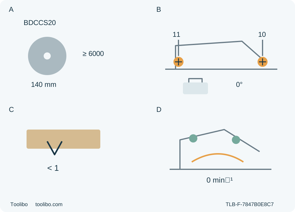
A identifies BDCCS20 and original 140 mm blade. B separates depth knob 11 from bevel knob 10 and detached battery. C shows less than a full tooth. D separates two designated grips, guard coverage and actual standstill.
A · Match the dated original system
Physical Type 1 and supplied June 2015 match; original approved 140 mm assembly, blade >=6000 RPM AND above actual nameplate.
B · Separate power and both knobs
Battery removed for setup; rear depth knob 11 and front bevel knob 10 are separate locks. Actual commissioned LBXR20/LCS20 only.
C · Verify actual partial tooth
Through-cut with less than a full tooth and clear supports; one-tooth wording does not override the stricter safety requirement.
D · Retain control through actual stop
Both designated handles, automatic guard in ordinary cutting, actual standstill/coverage before setdown and battery removal before acceptance. No timer readiness.
Original isolated recognition, not to scale, not fitting or charging. The printed 3/8-inch (10 mm) bore pair is a document identifier, not interchange permission. B requires both knobs secure after adjustment. C applies the stricter less-than-full-tooth safety requirement despite the one-tooth depth wording. D is not a live cut or brake timer: both handles remain controlled, actual full stop and guard coverage precede setdown, and battery removal precedes inspection. No native dust port is depicted.
This is an existing-owner workflow for a physically matched BLACK+DECKER BDCCS20 Type 1 and its supplied June 2015 instructions, not a guide to every current package carrying a similar name. The outcome is one manageable square crosscut in known dry wood, followed by an isolated check of the cut and the tool’s behavior.
The controlling document is 90609929 REV01, June 2015, a 52-page manufacturer manual available through the official Type 1 service route. Its English operating section is pages 1–15. The current BDCCS20C product page supports the product-family identity only: its body text includes reciprocating-saw and tool-free-blade claims that do not describe this documented circular-saw mechanism. There is no established current product-to-this-revision manual link. Match the physical type, controls and original supplied document before proceeding; a current package photo, charger field or headline speed does not close that gap.
1. Decide whether this exact system is eligible
Retain only the original approved wood blade and hardware already correctly qualified and installed for the actual saw. The dated manual specifies 5½ inches/140 mm and prints the bore as 3/8 inch (10 mm). Preserve that printed pair as a document identifier, not permission to treat nominal inch and metric holes as interchangeable or to add a bushing. Unknown blade approval, bore, washers, bolt, orientation or secure assembly means HOLD for qualified clarification before power is connected.
The blade must be rated for at least 6000 RPM under the blade-selection section, and its rating must also be above the actual tool-nameplate speed under the additional safety rule. Apply both conditions; the current product’s speed field cannot lower the dated manual’s blade requirement. This guide does not fit a blade, remove a knockout, select a replacement or teach bolt direction, spindle locking or tightening.
Use the owner’s already commissioned original LBXR20 battery and LCS20 charger, with their complete matching instructions. Both appear in the dated manual’s list. This is not a current carton promise or blanket POWERCONNECT interchange claim. No jack-charger substitution, new charging setup, LED diagnosis, tune-up or cell repair is taught. A pack or charger that has received a sharp blow, been dropped or otherwise damaged must not be used; obtain authorized assessment. Keep detached battery terminals protected from loose metal.
Do not use or store the tool and battery where the temperature may reach or exceed 105°F/40°C. Do not confuse that limit with the separate charging-temperature discussion. Charging readiness must already be established under the actual power-system instructions; this task begins with a sound, ready pack rather than charging it.
The outcome also depends on actual dust controls, not merely the absence of a hose. The manual requires suitable respiratory protection, ventilation and proper dust removal, with dust collection wherever possible. It does not establish a named native hood or universal port for this owner route. Before cutting, qualify the actual material, workplace and available approved dust-removal arrangement. If required capture or other exposure controls cannot be provided without an unsupported tool modification, HOLD and use another qualified system. A mask is not a universal substitute for an unresolved environment.
2. Isolate, inspect and reject faults before use
Release the trigger, allow complete standstill and make sure the lock-off is engaged to prevent trigger actuation. Before installing or removing a battery, the controls must remain in that non-actuating state. For removal, depress the battery release button and pull the pack out. Keep it separate during inspection, adjustment and workholding preparation. The automatic brake and lock-off do not replace physical battery removal.
Check the original blade for dullness, cracks, missing teeth, contamination or damage, and inspect the accessible mounting parts, base, handles and controls. Correct original hardware must be secure, not merely present. Bent parts, misalignment, binding, unusual noise reported during use or other abnormal operation require qualified service. Do not energize a suspect tool to reproduce a fault or use a scrap cut to validate questionable assembly. Keep the blade and handles clean under the complete maintenance instructions.
Before each use, check that the lower guard moves freely and closes instantly. With the battery removed, use its retracting handle to raise it, then release it and observe closure; verify no contact with blade or other parts at all angles and depths of cut. Check the spring and recheck after a drop. Do not clamp or tie the guard open. Missing, damaged, misassembled or sluggish guarding requires service before use. After setting the sample depth and zero angle, check that selected configuration again. During this ordinary edge-entry cut the guard must operate automatically, without a hand holding it open.
Check the isolated trigger and lock-off for normal movement and release. A switch that cannot turn the tool on and off, a defeated lock-off or an uncertain control is a service hold, not a reason to try repeated starts. Remove setup tools before reconnecting. The manual’s normal sound-tool on/off check comes later, after all static gates have passed; it is not fault testing.
3. Prepare clean wood, protection and a supported route
Choose a modest piece of sound, dry, untreated wood appropriate for the original blade. Inspect the whole route and retained material for nails, wire and other foreign objects. This saw’s intended-use section excludes metal, masonry, glass, tile, plastic and abrasive wheels. The sample also excludes unknown coatings, hidden services and installed construction. Do not turn the pocket-cut or laminate-sandwich sections into a new operation here.
Use a clean, well-lit, dry workplace away from flammable liquids, gases or explosive dust atmospheres. Keep children and bystanders away; inexperienced users require appropriate supervision. Wear ANSI Z87.1 eye protection (CAN/CSA Z94.3), ANSI S12.6 (S3.19) hearing protection and NIOSH/OSHA-approved respiratory protection suitable for the actual dust exposure. Everyday spectacles are not safety glasses. Keep hair, loose clothing, jewellery and gloves clear of moving parts. Provide ventilation and proper dust removal, directing particles away from face and body; operate any qualified collection system according to its instructions.
Clamp the retained work to a strong, stable, level platform. The wide portion of the shoe must remain on the supported material that stays after the cut. Support the offcut independently outside the blade path, near the cut and outer edge as needed, so it will not sag, twist, trap the blade or fall toward it. It must still be free to separate; do not clamp across the kerf. Never hold stock on a knee, in a hand or against the body, and never catch the cut-off piece.
Mark the wanted end from a reliable reference and identify the waste side. Put the appearance face where the manual’s top-side splintering warning will not spoil the intended result; the sample verifies finish rather than promising a clean face. Any clamped straightedge must match the actual shoe-to-cut relationship and remain clear of the motor, guard, both handles and every support. Do not invent a factory offset or a notch-side rule from another model.
With the battery removed and blade guarded, check reach and clearances beside or safely above the planned path, without tooth contact. Both hands must remain on their handles through the full cut and clear exit. The base cannot lose its retained-side support, and clamps must not need moving mid-cut. If the actual arrangement cannot satisfy those conditions, replan or obtain precut stock rather than recut a small loose piece. No universal overhang or support-load limit is supplied here.
4. Set the two knobs and verify real depth
Keep the battery removed. The rear depth-adjustment knob is item 11; the front bevel knob is item 10. They are separate locks. Loosen the front bevel knob, set the shoe to zero on the actual angle scale and tighten it securely. The original blade-to-shoe square alignment must already be correct. This guide does not loosen the jam nut, turn the stop screw or use a powered cut as a calibration procedure.
Loosen the depth knob, move the shoe to the depth needed for the actual stock and retighten it to lock the shoe. The scale is a reference, not proof of safe projection. Pages 7 and 12 describe one tooth below the work, but page 3 expressly requires less than a full tooth. Use the stricter condition: an actual through-cut with less than a full tooth visible below the material, while clearing every support and clamp beneath it. Do not accept an entire exposed tooth because a diagram or nominal scale seems to show one.
Recheck both knobs, actual depth, zero setting, guard movement and complete travel. A setting that shifts, cannot be locked or requires the blade to strike a support is not ready. Plan the cut line and guide from the actual setup; the finished end will be measured afterward, without a promised dimensional tolerance.
5. Check normal switching, then make the cut
Confirm the trigger is released and the lock-off blocks actuation before inserting the qualified battery. Seat the pack fully and ensure it is fully latched. Do not force a mismatched pack or proceed with uncertain retention. Keep any dust-removal equipment ready and active as required by its own instructions and the actual environment.
The General Cuts section requires checking normal on/off function with the battery inserted. Only after all isolated checks pass, hold the sound tool securely with both hands, lower guard closed and blade clear of stock and surroundings. Press and hold the lock-off from either side while depressing the trigger; release the trigger to switch off, retaining control through complete standstill. If normal switching fails, stop, isolate when safe and obtain qualified service; do not repeat an energized fault test. Complete this check before positioning for the sample.
For the cut, hold the main handle and secondary handle firmly, keeping hands away from the cutting area and underneath the work. Use the insulated gripping surfaces where electrical contact hazards are relevant; this route excludes hidden wiring. Position the body to either side of the blade line, not in line with it. Place the shoe on the supported retained work with the blade clear of the material and align the marked route.
Press the lock-off from either side and keep it pressed while depressing the trigger. Once the tool is running, the manual allows release of the lock-off, but the trigger must remain held. There is no lock-on provision; never secure the trigger in the on position. Let the blade run freely and reach full speed before contact, rather than treating a fixed number of seconds as proof. Apply gentle forward pressure with the shoe flat and both grips maintained. Do not force slowing, twist the saw back onto a drifting line or reach toward waste.
6. Observe actual stop and accept the sample
After the planned complete cut, release the trigger and keep control until the blade has stopped completely before withdrawing it. Confirm lower-guard coverage before setting the saw down, then remove the battery before measuring or touching the work. End pieces may be hot, sharp or heavy; let them cool and handle them carefully after isolation. The automatic brake’s stated one-to-two-second behavior is not permission to touch or move a still-turning blade, nor a substitute for guarding.
If the blade binds, stalls, wanders or the tool abruptly shuts down, release the trigger immediately and hold the saw motionless in the material until full standstill. Never pull a moving blade backward or lift it out of a trapped kerf. Isolate before assessing the cause. This guide does not supply a cooling/recharging reset, an old-kerf restart or a forced-release method. An unexplained shutdown or abnormal operation requires qualified assessment before another task is planned.
After cooling and isolation, inspect both faces, the cut edge and the retained reference. Check length, square, straightness, splintering, burning, clamp movement and any evidence of rubbing or binding. Accept only if the result meets the stated project need and the guard, controls, blade and support behaved normally. Record a failed result and hold the work for correction rather than repeatedly trimming a loose short piece. A clean-looking face does not prove a questionable tool safe.
7. Put the system away without expanding the repair scope
Remove the battery before care; unplug the charger before cleaning it or handling its maintenance needs. Use only the prescribed mild soap and damp cloth for accessible tool surfaces, preventing liquid entry and never immersing any part. Repairs or adjustments outside the manual belong to authorized or otherwise qualified service personnel using identical replacement parts. Protect battery terminals and store the system securely away from children and excessive heat.
The manual’s generic recycling passage says batteries are integrated, while its model-specific battery instructions clearly show a removable cartridge. This workflow follows the explicit operational removal instructions and does not teach opening the tool or internal battery removal. Similarly, charger tune-up, generic cord and battery-chemistry passages are not authority to improvise another power system. The completed outcome is a documented, correctly scoped sample and a ready-or-hold decision for the actual dated owner system, not a current-kit or universal compatibility claim.
Models referenced