
Plan the pilot-to-driver change outside the gap
A drill and dashed battery envelope inside a cabinet lead to an external bench with separated battery, then a short driver approaching a screw.
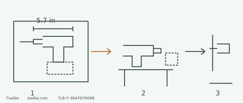
1 · Measure the drilling assembly
Include bit, measured battery template, hand clearance and the entire withdrawal route.
2 · Stop and isolate outside
Use a stable changing place; remove the battery before changing accessories or settings.
3 · Recheck the driving assembly
Check the new holder length, choose low range and tested clutch, then restore and latch the battery with finger off trigger.
5.7 inches refers to the published body length only. Conceptual layout, not scaled assembly dimensions or permission to work with the battery connected during a change.
Check the assembly, not just the 5.7-inch body
US 3601-20 product information lists a 5.7-inch length and 2.3 lb bare-tool weight. These are not the dimensions and weight of your battery-and-long-bit assembly, or a guarantee of room inside a cabinet or around your wrist.
If a battery is smoking, unusually hot, leaking or swollen, do not approach or handle it for a space check. Otherwise record the battery model, bit or holder, clamps and working posture. For normal equipment, release the trigger, wait for a complete stop, lock the direction and remove the battery before installation or static checks.
Measure the undamaged battery separately and add its length, width and height to side and top drawings of the disconnected body using the mounting reference. Never bridge contacts with a metal ruler. A cardboard outline is for space comparison, not insertion into the battery interface. This accounts for the widest part underneath without energising the tool inside the cabinet.
Measure four stages of the route
Swipe or scroll horizontally to see all columns.
| Stage | Specific check | If it fails |
|---|---|---|
| Entry | Opening, rails and clamps clear the body, accessory and battery envelope | Change the route or move suitable work to a bench |
| Working | Fingers can release the trigger; feed clears the floor and rear obstruction | Rearrange the work rather than side-loading the bit |
| Withdrawal | The bit can leave the hole fully and the stopped tool can be removed | Do not begin a job without an exit |
| Change and return | A stable external changing place exists; the new holder’s length also fits | Choose a suitable verified alternative combination |
Use measurements of the real combination. If a correctly clamped pilot-drill assembly measures 250 mm from tip to tail but only 240 mm of straight space exists behind the hole, it fails. Those numbers illustrate the method; they are not fixed 3601-20 specifications. A shorter driving assembly does not make the initial pilot-drilling stage fit.
Select a range for each operation
The top selector shows 1 for low and 2 for high, with no-load ranges of 0–550 and 0–1,700 rpm. Wait for a complete stop before shifting and engage the slider fully. No-load values are not a recommended cutting-speed table.
For screws, the manual specifies low range, then a numbered clutch setting established on matching scrap. Wood drilling uses drill mode, starting slowly and increasing according to the bit and material; use low speed for low-melting-point plastics. Metal work also requires suitable cutting accessories, lubrication and support. Moving the slider to 2 does not complete that preparation.
3601-20 lacks the hammer action of 3602-20. Numbered clutch settings and the drill symbol serve different tasks. Do not leave the tool in drilling mode for driving screws just to avoid changing it.
Follow the complete pilot-hole-to-screw sequence
- With power disconnected, install the suitable pilot bit and choose drilling mode and the appropriate range. Secure the work and resolve space, material and concealed-service conditions. Install and latch the battery with your finger off the trigger, then release the centre lock and select forward rotation appropriate to that bit.
- Hold the tool securely, place the bit against the work and begin slowly. Work along the axis with controlled feed appropriate to the accessory and material; do not bend the bit to dodge an obstruction.
- When finished, withdraw the bit, release the trigger and wait for a complete stop. Move the tool to the reserved stable changing place, lock the direction and remove the battery. Avoid touching a bit that may still be hot.
- Fit and correctly clamp the matching driver or holder. Recheck the new assembly’s space, then select mechanical speed 1 and the numbered clutch setting verified on scrap.
- Clear loose items, reinstall and latch the battery with your finger off the trigger, then release the centre lock, select the correct driving direction and return to the work to observe screw seating.
Do not force completion when clearance disappears
Release the trigger and wait for a stop if the body touches an obstruction, fingers become trapped, the bit visibly deflects, the driver slips or the tool stalls. Inspect only once safe removal and power isolation are possible. Do not twist the drill while pulling the trigger in a loaded, confined gap.
Possible alternatives include refixing a movable workpiece, changing a suitable work sequence or choosing another tool explicitly appropriate for the task. Less shank engagement, removed safety parts and unsuitable adapters are not ways to gain space. The goal is a complete workable route, not merely a photograph of a drill that fits inside.
Models referenced