
Compare the trial joint with the finished joint
Two matched sample sections show the same screw and fitting, while separate control symbols distinguish numbered clutch adjustment from a crossed-out drill mode.
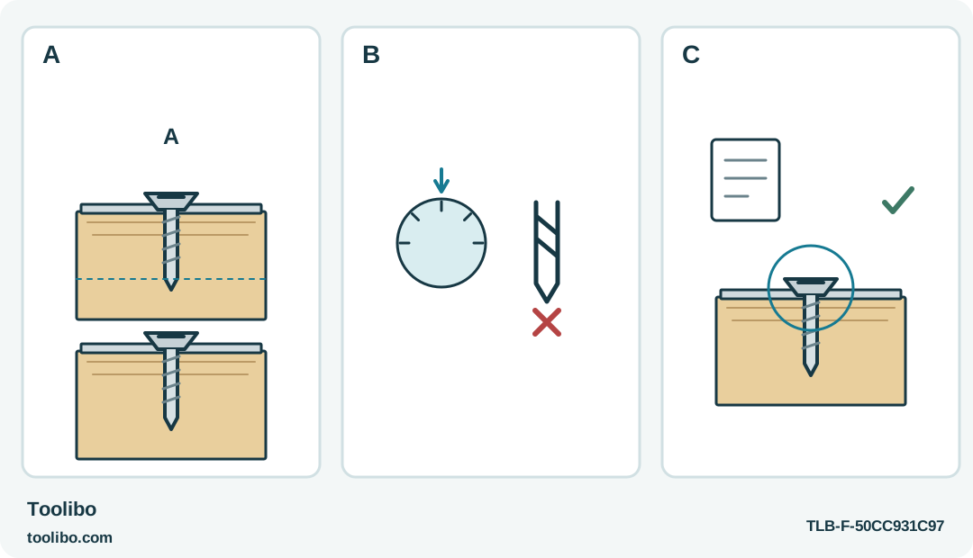
A · Match screw and material
Reproduce the screw, fitting, material and hole arrangement on a supported sample.
B · Use the numbered clutch
Keep the trial in gear 1 with a numbered clutch setting; the drill-symbol bypass is excluded.
C · Inspect before transfer
Inspect the result before transferring the arrangement; no diagram prescribes a universal clutch number.
A matching sample tests the fastening arrangement. The diagram does not prescribe a clutch number or a certified tightening torque.
Make the trial answer a real question
The useful question is not which clutch number looks right. It is whether the chosen setup seats the specified screw without damaging the material or fitting. A DF012D trial should reproduce the important parts of the real joint: screw type and length, material, pilot-hole arrangement and the surface beneath the head. A random screw in an unrelated offcut tells you little about a delicate furniture fitting.
Wear suitable eye protection and keep bystanders away before beginning powered fastening. Keep loose clothing, hair and fingers clear of the rotating bit.
Work on an ordinary, non-structural joint whose fastening method is already specified. If the furniture maker gives a final tightening requirement or requires hand tools, follow that instruction rather than substituting a trial result. Keep chair frames, wall supports and other safety-critical assemblies out of an informal practice exercise.
Support the sample securely and mark it clearly as a test piece. Keep enough space around the intended screw position to see whether the surface crushes or the material splits. Do not hold a small test block loose in the hand while driving into it.
Prepare the tool with the battery removed
Release the switch, set the lock lever to its locked B position and remove the battery before fitting the driver bit or adjusting the setup. Use a bit with the shank geometry shown in the DF012D instructions, not merely any accessory described as quarter-inch hex. Pull the sleeve, insert the bit fully, release the sleeve and verify retention. If the sleeve does not return or the bit comes out, correct the fit before installing the battery.
Choose a grip shape that leaves a straight approach to the screw. Keep fingers clear of the pivot while changing between straight and pistol configurations. The pivot is an access feature, not a reason to keep readjusting the tool while it is engaged with a fastener.
Inspect the screw recess and seat the bit by hand with power still isolated. A good clutch setup cannot protect a screw head from a mismatched or worn tip. Refit or replace the bit if the contact is poor.
Choose a gear and a numbered clutch position
The DF012D has two gears and numbered clutch positions. Change gears only when the motor is stopped, and engage the selected position fully. For this controlled fastening trial, select gear 1, the low-speed position, and begin at a low numbered clutch setting. Keep gear 1 throughout this procedure and assess the result rather than jumping to maximum.
The drill-symbol position is not the next fine adjustment above the numbers. It bypasses the clutch, so it is outside this controlled-clutch procedure. Also, the available clutch auto-stop range depends on the gear and setting. Do not assume every numbered position behaves the same in both gears.
Install the correct charged battery only after setup is complete, keeping the lock lever at B until ready to operate. Confirm gear 1, then move the lever to the unlocked A position and check the intended direction before placing the tool on the screw. Return the lever to B whenever you are not operating. If the battery or tool shows damage, stop instead of treating the sample as a way to test a suspect power system.
Run the sample in deliberate steps
- Start the intended screw in the matching sample using the fastening method specified for that joint.
- Engage the bit fully and hold the driver in line with the screw. Keep hands clear of the screw path and rotating parts.
- With gear 1 selected, drive until the clutch stops the motor or until the intended seat is reached, whichever comes first. Release the switch when the motor stops and set the lock lever to B before inspecting the work.
- Inspect the screw head, fitting and material. If the screw stopped short and the joint remains sound, increase the numbered setting cautiously and repeat on an appropriate fresh test location.
- Reject any setup that crushes the surface, strips the hole, damages the recess or pulls the parts out of alignment. Do not conceal that result by simply testing another screw beside it.
Record the gear, clutch position, screw and sample material together. A bare note saying “setting five” is not transferable to a different screw or a different board. A passing sample is a useful starting point, not a torque certificate for every fastener in the project.
Transfer the result and stop when the joint changes
Use the same supported approach on the finished piece, watching the first actual fastening closely. Stop if the resistance, alignment or seating differs from the trial. The finished part may have a different hole condition or a thin decorative layer that the sample did not reproduce.
Do not repeatedly squeeze the switch after an automatic stop to force the screw farther. Decide first whether the screw has reached its correct seat or whether something is wrong with the joint. Likewise, a low-battery stop is not a signal to change to the drill symbol and continue.
Set the lock lever to B and remove the battery before changing bits, adjusting the work arrangement or putting the tool away. Keep the successful sample and its note until the project is finished. They provide a concrete comparison if a later fastener behaves differently, and help prevent the common mistake of blaming the clutch for a damaged hole or an incorrect screw.
Models referenced