
Shelf-pin rows: keep one reference end when extending a KMA3232 pattern decision map
Four hole rows share a top datum across paired panels; an enlarged extension separates an indexing pin from drilling bushings and crosses out drilling through its unbushed hole.
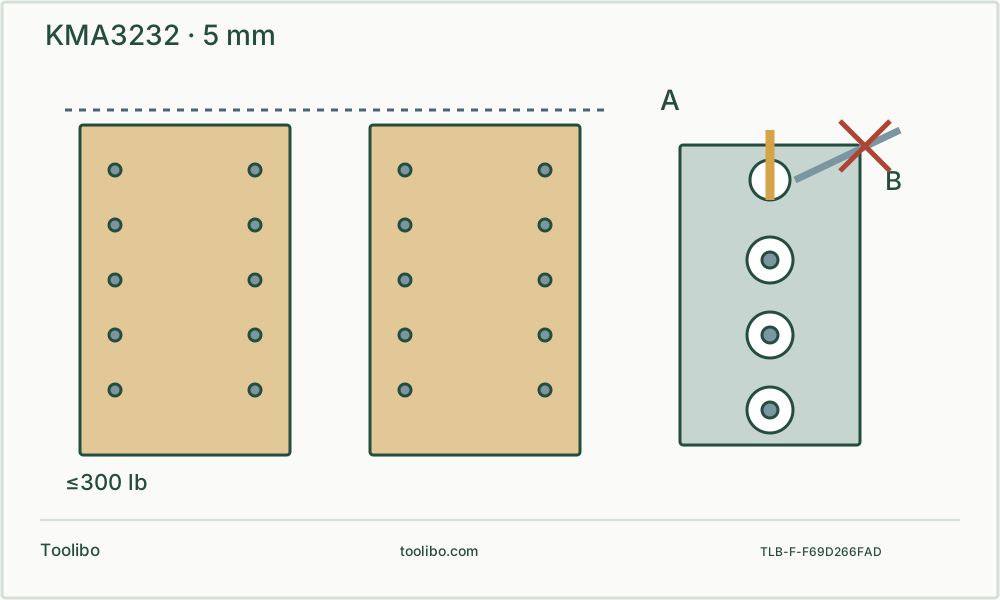
Datum
Keep one reference end across left, right, front and rear rows.
Index
Register the extension with the last verified hole, then clamp.
Check
Test all support points together without heavy loading.
Original paired cabinet-side diagram uses a common top datum across four hole rows; an enlarged extension shows an indexing pin in the previous hole and a crossed-out rotating bit at the unbushed extension hole.
Define the four rows before drilling any of them
This guide covers the Kreg KMA3232 5 mm shelf-pin jig on accessible, removable cabinet-side samples. Check the exact jig and pin size: a quarter-inch pin is not a 5 mm pin. The purpose is to align left, right, front and rear support locations, not to design a shelf’s load capacity. Shelf span, material, pin type and cabinet construction need their own specification.
Mark the inside face, top and front edge of both side panels. Draw a simple row plan before turning the second panel over. A mirrored cabinet side must preserve the intended inside face and common height datum. If each row starts from whichever corner is convenient, four individually neat rows can still leave a shelf rocking.
Set the collar with the jig’s own calibration geometry
Disconnect drill power. Slide the specified stop collar onto the matching bit, then place both into the storage slot on the back of the jig. The bit end goes into the hole at the slot edge until it stops, and the collar sits in the slot recess before its set screw is tightened. That is the manufacturer’s reference method, not a generic tip-to-collar distance.
Check the bit and collar have not been replaced by a different-length combination. Confirm the sample’s thickness leaves a safe back face with this matched setup. The collar controls travel relative to the guide; it cannot recognize a thinner panel or a recess machined into the far side. Test the actual layered or veneered stock, not only a solid block.
Choose the cabinet arrangement and a repeatable datum
The manual distinguishes face-framed and frameless cabinets. For the frameless setup, fit the fence in the base and slide it to secure it. Use the same reference end of the jig throughout; the manufacturer recommends the top when extending downward. When moving from front to back, the fence changes side, but the common height reference must not change.
Clamp the jig and work securely in the specified clamping region. If using connected jigs, clamp both. The manual states a 300 lb clamping limit; that is a maximum boundary, not a force to aim for. This guide uses removable parts that permit clamping and does not adopt a hand-held shortcut in a difficult assembled cabinet.
Drill the first sample set, then inspect
Fit the prepared bit and stop collar with power isolated. Confirm ordinary rotary mode, clearance and suitable dust controls, and keep hands outside the bit path. The matched guided procedure starts the bit inside the guide and brings it to speed before contacting the wood. Feed until the collar meets the guide; do not continue pushing after the stop.
Withdraw according to the manual while the bit is still rotating, then stop completely before moving the jig or touching chips. After isolation, inspect the first holes and test the actual 5 mm pins for appropriate fit. Check the back face for damage. A pin fitting one shallow hole does not establish that every row is at the same height.
Extend by indexing, not by measuring from the last guess
After the first set, unclamp, connect the extension at the jig’s top and align its indexing hole with the last completed shelf-pin hole. Put the indexing pin through the extension into that hole, then clamp the jig again before drilling the next set. The extension hole has no drill guide: never use it as a drilling bushing.
Before continuing, check the extension is fully connected, the indexing pin is seated without forcing and the jig has not rotated away from the panel edge. A damaged or oversized first hole can become an unreliable datum. Stop and correct the cause rather than copying its error down the entire panel.
Validate a complete support level
Swipe or scroll horizontally to see all columns.
| Check | What it catches |
|---|---|
| Same top reference on both panels | A whole row shifted vertically |
| Matching front and rear locations | A shelf tilted or twisted front to back |
| Actual pins inserted without forcing | Wrong bit, pin size or damaged holes |
| Trial shelf supported on all intended pins | A mismatch hidden by checking only one row |
Use a light trial assembly to inspect alignment, not a person or heavy load as a test weight. A rocking shelf may reflect pin height, row location, shelf flatness or cabinet squareness; do not immediately enlarge holes. Record the reference end, fence side and bit identity for the accepted setup. Stop for moving guides, a slipping collar, binding or unexpected breakthrough, and isolate before investigation.