
Blind pilot holes: distinguish usable hole depth from the drill tip decision map
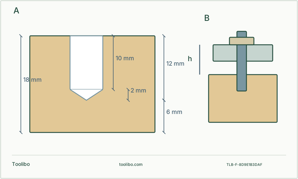
A section labels an illustrative 18 mm panel, 10 mm cylindrical bore, 2 mm tip projection, 12 mm deepest reach and 6 mm remainder; a second section separates guide height.
Meaning
Separate usable bore depth from deepest tip reach.
Reference
Include the guide and use its matched stop method.
Proof
Inspect a matching sacrificial sample before the finished panel.
Original dimensioned cross-section distinguishes the 10 mm cylindrical bore, 2 mm tip projection, 18 mm panel and 6 mm nominal remainder; another view separates guide height from penetration. Numerical example is illustrative, not a prescribed setting.
Define what the hole must achieve
This is a planning and sample-inspection method for a small rotary-drilled blind pilot in a removable, known wooden cabinet part. It is not a universal depth setting, structural fixing design or a method for drilling an assembled wall. Obtain the screw or hardware maker’s required pilot diameter and depth, and confirm the drill, bit and any depth guide are suitable.
Ask whether the specified depth means the deepest tip position or a usable full-diameter bore. A pointed drill does not leave a perfectly flat bottom. If a fitting needs a certain cylindrical depth, stopping the point at that number may leave too little usable hole. Conversely, allowing extra travel for the point can break through a thin panel. Resolve the meaning before marking the bit.
Measure the actual remaining thickness
Measure the real panel at the intended location, not just the material’s nominal label. A groove, rebate, hinge recess, curved back or previous repair can reduce the local thickness. Inspect both faces and remove loose chips from the measurement surfaces. A hidden void or unknown composite construction can make a simple thickness measurement misleading; do not guess through it.
Mark the face that will be drilled and the opposite face that must stay intact. Keep the sample oriented the same way. A thick offcut of another material is not a valid proof for a thin finished panel. Include any surface layer whose damage would be unacceptable, such as a decorative veneer on the back.
Use a depth budget, not one isolated mark
Consider a calculation example, not a recommended drilling setting: a sample is 18 mm thick, the intended usable cylindrical bore is 10 mm, and the actual bit point projects a measured 2 mm beyond that bore. The deepest point would then reach 12 mm, leaving a nominal 6 mm before the far face. That arithmetic does not establish that the hardware, wood or remaining thickness is adequate; it merely exposes what needs checking.
Swipe or scroll horizontally to see all columns.
| Quantity | Example | What to verify |
|---|---|---|
| Local panel thickness | 18 mm | Measure at the real hole position |
| Usable cylindrical depth | 10 mm | Confirm the hardware requirement |
| Extra point projection | 2 mm | Measure the actual bit geometry |
| Deepest reach / nominal remainder | 12 / 6 mm | Allow for setup variation and inspect the sample |
Do not invent a universal safety margin from this example. Different bits, end shapes, materials and hardware change the result. If the required hole cannot leave an acceptable intact back, change the hardware or construction rather than relying on exceptional trigger control.
Include the guide above the wood
A stop collar touches a guide, not necessarily the wood face. The distance from the collar’s contact surface to the bit tip must account for everything between that stop and the work. The KMA3232 shelf-pin jig, for example, sets its matching bit and collar in a built-in recess; the KHI-HINGE uses a different custom shoulder reference. Do not transfer one device’s collar measurement to another.
Use a stop only when compatible with the actual bit and guide. A tape flag can warn visually but is not a positive mechanical limit and may move or become hidden. Tighten and inspect the matched collar as directed with power removed. Replacing the bit or changing how far the shank enters the chuck can invalidate an improvised reference, so repeat the check after any change.
Drill and inspect one sacrificial sample
Clamp the sample and suitable support securely, keeping hands and the bench out of the complete bit path. Arrange eye protection and wood-dust controls. Fit the bit with power isolated, select rotary mode and follow the exact accessory’s starting procedure. Keep the axis steady; tilting changes both hole shape and the deepest local reach.
Stop at the verified limit without pushing against it to force extra depth. Wait for a complete stop and isolate before measuring or clearing chips. Check the actual depth with a suitable non-cutting gauge, inspect the far face and trial the specified hardware gently. Do not use the powered bit as a depth probe or force a fitting to prove the hole is deep enough.
Recheck before the visible piece
Record the panel thickness, bit identity, reference surface and accepted stop arrangement. Recheck collar security, guide seating and sample agreement after repositioning. If the first hole is too shallow, find out whether the point geometry, debris or reference was misunderstood before simply lowering the stop.
Unexpected breakthrough, a moving collar, splitting or a rocking guide means stop and revise the setup. A spare screw should not be driven farther to conceal the error. This process succeeds when the hardware requirement and the intact far face are both verified, not merely when the drill stops at a mark.