
Three modes, three different jobs
Numbered clutch, drill-bit and hammer concepts are separated, with the Type 1 masonry capacity beneath the hammer column.
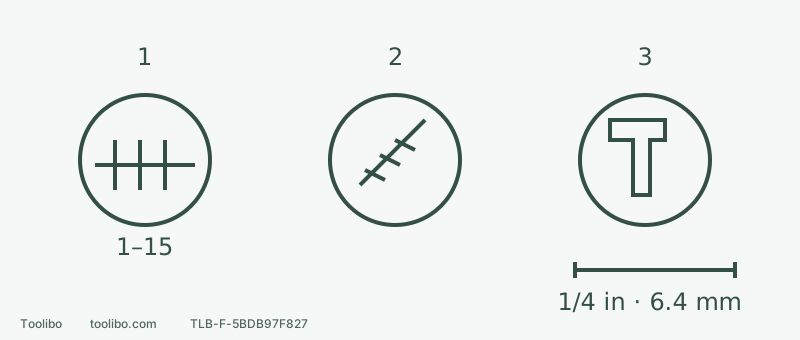
1 · Numbered clutch
Trial ordinary screws on matching scrap; numbers are not calibrated torque units.
2 · Rotary drilling
Select suitable wood or metal accessories; the numbered clutch does not govern this mode.
3 · Verified percussion task
Check material, percussion-rated bit, capacity, depth, workholding and dust control before selecting the hammer.
Conceptual mode symbols, not exact collar artwork. The masonry value applies to the cited US Type 1 manual and does not clear a wall or fixing design.
Turn “a hole” into a defined job
Write down the material, diameter, depth, purpose, accessory model, workholding and dust controls. A load-bearing fixing also needs a suitable fixing-system design for that substrate. Making a hole does not establish its load capacity.
Brick, concrete and block require their own checks; do not choose a material description by appearance alone. Unknown coatings, concealed services or structural conditions require assessment before disturbance, not an exploratory hole. Set up the dust-control solution before starting rather than connecting an ordinary vacuum after dust appears.
Use the 1/4-inch example as a check, not a guess
The US DCD800/DCD805 Type 1 manual NA229093 lists 1/4 inch (6.4 mm) for DCD805 under carbide masonry bits. The corresponding DCD800 cell is a dash. Shared instructions do not give the two machines identical masonry capacity.
Suppose an assessed brick substrate may be disturbed and the planned hole is 1/4 inch. The candidate bit explicitly supports that brick material and percussion drilling. Its diameter does not exceed the listed value, but the remaining checks still matter:
Swipe or scroll horizontally to see all columns.
| Check | Required answer | If missing |
|---|---|---|
| Tool version | The actual drill matches the US Type 1 DCD805 | Find its applicable manual first |
| Material and accessory | The bit supports the substrate and percussion operation | Change the accessory or method |
| Shank and depth | Correct chuck engagement and depth within accessory limits | Do not gain reach by gripping less shank |
| Work conditions | Stable workholding, services and coatings assessed, dust controls established | Do not start |
This is a checking example, not a hands-on test. An 8 mm masonry hole exceeds this manual’s stated recommendation even if the 13 mm chuck accepts the bit. A larger value from another market or revision cannot simply replace it.
Understand the three collar choices
Numbers 1–15 are screw-driving clutch settings. Higher numbers allow greater driving torque, but they are not a calibrated N·m scale. The drill symbol selects rotary drilling; wood and metal work should not use the hammer symbol. Hammer mode is for verified suitable percussion work with carbide-tipped or masonry bits rated for that operation.
Neither drilling nor hammerdrilling releases according to the numbered clutch setting. A bind can produce sudden reaction torque. Do not assume the clutch behaviour from a screw-driving trial remains active. DCD805 is a conventional-chuck hammer drill, not an SDS rotary hammer and not a chiselling tool.
Set up only after the task checks pass
A smoking, swollen, leaking or unusually hot battery is a reason to stop without approaching or handling it to follow these steps. For normal equipment, release the trigger, wait for a complete stop, lock the direction and remove the battery before installing the suitable bit or adjusting controls.
Rotate the mode collar until the hammer symbol aligns with the arrow. Choose the mechanical range for the specific accessory and operation, engaging the selector fully. There is no single high-speed answer for every masonry material, diameter and bit. Secure the work and confirm holding and withdrawal space. Remove adjustment tools, then install and latch a compatible battery with your finger off the trigger.
Recheck the material and dust arrangement before starting. Apply controlled force along the bit axis. Excessive pressure, sideways levering or holding unstable work against your body cannot compensate for slow cutting.
Know when the answer becomes “stop”
If the bit fails to cut, the tool repeatedly stops, the body twists noticeably, the grip slips or dust control fails, release the trigger and wait for a stop. Do not repeatedly tap the trigger to force through, or change range, direction or touch the bit while it moves.
Once safe handling and power isolation are possible, reassess accessory suitability, wear, engagement and changed conditions. Unexplained problems need the appropriate professional. If the actual material differs from the assessment, return to that assessment rather than fitting a larger bit. This guide helps select a mode and verify a configuration; it does not replace structural work planning or fixing-system design.
Models referenced