
Read the nameplate and measure the route
Confirm the actual DWE6423 electrical rating and applicability of the North American instructions. Its listed current is 3 A; this example is only for the matching 120 V condition. Another voltage printed in a generic table is not permission to supply the tool at that voltage.
Measure the actual extension route, clear of moving abrasives, sharp edges and crushing points, with room for normal movement. A connector should not carry the tension of a taut lead.
Read the row and column together
In N412818, APR15, 3 A falls in the row greater than 0 and not greater than 6 A. The 120 V length columns give:
Swipe or scroll horizontally to see all columns.
| Total extension length | Minimum conductor size for this condition |
|---|---|
| 25 ft / 7.6 m | 18 AWG |
| 50 ft / 15.2 m | 16 AWG |
| 100 ft / 30.5 m | 16 AWG |
| 150 ft / 45.7 m | 14 AWG |
Smaller AWG means a thicker conductor. The table does not establish outlet suitability, reel condition, connector quality, environmental approval or local electrical compliance.
Work through a 50-foot example
For the matching nameplate and supply, locate the 0–6 A row and 50-foot column: 16 AWG. Read the cable’s actual markings and other requirements, rather than judging its outer diameter.
If a 25-foot section is extended by another 25 feet, the total is 50 feet. Each section must meet the minimum size for that total; a thicker section cannot compensate for a thinner one. This explains the rule, not a recommendation to chain leads. Prefer an appropriate single arrangement over unverified connections.
Keep the SKIL documentation gap separate
SR211601 is specified at 120 V, 60 Hz, 2.8 A and SR250801 at 120 V, 60 Hz, 1 A. Their checked extension tables begin at 3–6 A, without an explicit row for either rating. Copying DEWALT’s table does not supply a missing SKIL instruction.
Ask SKIL or a qualified electrical professional using the actual rating, required total length and environment. If a suitable extension arrangement cannot be established, reposition the work or use another confirmed appropriate arrangement rather than invent a value.
Inspect before energising
Unplug the tool and inspect plug, cable and strain relief for cuts, crushing, looseness or heat damage. Do not tape over damaged insulation, modify plugs or defeat protection. Outdoor leads must be suitable outdoors; keep dry-sanding equipment out of rain and wet conditions.
Confirm the switch is OFF before connecting. Loss of speed, hot connectors, burning smell or repeated protective trips requires stopping and safe disconnection, not repeated resets. Supply, outlet or tool uncertainty needs qualified assessment, not live probing.
Use the full extension length
The bracket spans the complete extension run in both drawings; joining lengths does not restart the gauge calculation.
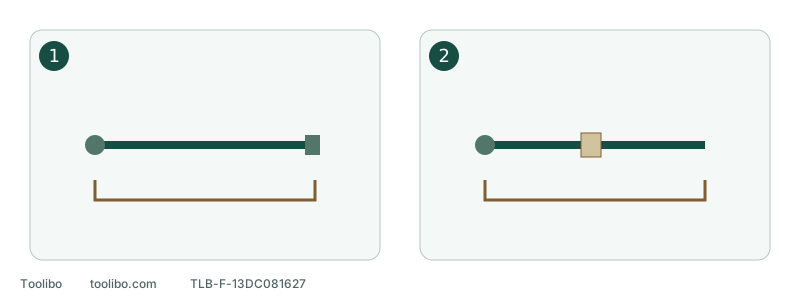
1. One continuous lead
Read the table using the nameplate and the full required length.
2. Multiple segments
Every segment must satisfy the requirement for the combined length; this is not a recommendation to join leads.
The bracket spans the complete extension run in both drawings; joining lengths does not restart the gauge calculation.
Models referenced