
Glass and the intended endpoint
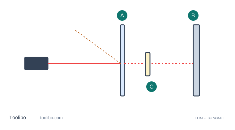
Original schematic: The visible glass face is one possible boundary. A return may involve another surface. Use a defined target plane or a direct method. Not to scale.
A
The visible glass face is one possible boundary
B
A return may involve another surface
C
Use a defined target plane or a direct method
Conceptual geometry only, not to scale. The diagram does not establish installation clearances or reproduce a manufacturer control layout.
Identify the boundary, not just a visible red dot
A glass door, mirror or glossy cabinet can make a household measuring task deceptive. You may see a spot while the measurement does not represent the surface you intended. Transparent material can allow light to reach something behind it; reflective material can redirect light rather than behave like an ordinary painted wall. The exact response depends on the instrument and conditions, so a plausible number is not proof of the correct endpoint.
Begin by naming the desired boundary: the front of the glass, a cabinet frame, the wall behind it or the clear opening when the door is open. These are different dimensions. Inspect the scene from a safe position and decide which physical surface a direct method can reach. Do not look along the beam through binoculars or other optical instruments, and never use a person’s body as a convenient target.
Prefer a direct measurable feature when it answers the question
For a cabinet fit check, the relevant boundary may be the frame rather than the glass panel. A tape can often establish a short frame-to-frame distance more clearly than a laser shot aimed at the glazing. If the desired dimension is the wall behind a glass-fronted object, measuring to the front face and calling it the wall distance is not acceptable. Use another accessible baseline or a suitable direct method.
Opening a door can change the measurement path, but it does not guarantee that the next return is the intended wall. Check that the beam does not continue through another doorway or strike furniture. Restore a stable, opaque target where appropriate and safe. Avoid moving heavy glass, removing fixed panels or disturbing a large mirror merely to improve a routine room measurement.
Understand the limits of a temporary target
A suitable matte target at a clearly defined plane may help establish a usable endpoint. Follow the meter’s instructions and avoid attaching anything that could damage the surface. Secure the target before taking a reading, with nobody in the beam path. If its front face lies in front of the desired boundary, that offset must be measured and accounted for explicitly.
Do not assume that a piece of paper makes every transparent or reflective surface equivalent to a normal wall. Its position, stability and relationship to the required plane still matter. Nor should you treat several identical returns as proof that the reading reached the intended layer. Repeatability can occur at the wrong surface. Verify a representative distance with an independent suitable method when the result matters to an order or fitted component.
Diagnose the target before blaming the instrument
If measurements are inconsistent only at glass or a mirror, compare performance on a straightforward opaque indoor surface within the exact model’s operating conditions. Keep the reference and support correct. If the simple span is consistent, the difficult target remains a plausible explanation, but this is not a formal calibration test. If instability also occurs under straightforward conditions, follow the manufacturer’s specified checking and service advice.
Record the target description and any external target arrangement alongside the affected result. This prevents a later reader from treating a derived or uncertain dimension as a direct measurement to a solid wall. Keep uncertain values out of fabrication instructions until they are resolved. A mirror can also conceal the actual wall condition, which a distance meter does not investigate.
Never respond to a poor return by aiming toward people, viewing the beam through magnifying optics or changing internal laser components. Do not tape over receiving optics or invent a filter arrangement. The useful choice is often between a well-defined external target and a different measuring method, not between increasingly elaborate attempts to force the instrument to interpret the scene. A short, directly checked frame dimension is better than an impressive-looking long reading whose endpoint you cannot establish.
Models referenced