
Sharp, rounded and obstructed corner contacts
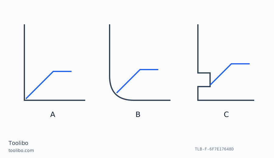
Three corner profiles show an endpiece touching a sharp corner, a rounded finish and a projecting obstruction.
A
A sharp internal corner may offer a reproducible contact.
B
A rounded finish can stop the tip before the imagined intersection.
C
A projection can obstruct the hinge or housing.
Automatic endpiece recognition does not establish that the physical tip reached the intended geometric point.
Identify the generation before opening the endpiece
This guide concerns the discontinued DISTO D2 v1 identified by Leica’s US product listing and D2v1 manual directory. It is not an instruction sheet for a newer D2 or D2G. On this documented generation, the folding multifunctional endpiece helps reach a corner, and the instrument automatically adjusts its reference when the endpiece is positioned as described in the manual. Automatic detection does not establish whether the tip is touching the point you intended.
Before measuring a recess, unfold the endpiece according to the matched instructions. Check the reference indication and look at the actual contact. The tip must reach the intended corner. If the hinge or housing meets a plaster projection first, the physical starting point is different. Do not force the endpiece against uneven masonry to make the display agree with a previous measurement.
Compare the same pair of endpoints
Draw the starting corner and target on a simple plan. For a diagonal, identify the corresponding opposite corner rather than an arbitrary point on its skirting. Take a reading, lift the instrument away, and place it again. This tests whether the physical contact can be reproduced. The endpiece can make a starting point accessible; it cannot turn an uncertain target into an exact endpoint.
A recess may be narrower at the front than at the back. Record those positions separately and include the height of each measurement. A long diagonal alone does not establish that a cabinet opening is rectangular or that a rigid object will fit through it. Check width, depth and local obstructions directly before ordering an expensive component. Keep the purpose of each reading attached to its position rather than collecting a list of unexplained numbers.
Preserve the reference rather than inventing a correction
When returning to an open wall, place the instrument for the intended measurement and inspect the reference indication again. Do not routinely add or subtract an estimated endpiece length. If moving the endpiece produces an unexpected change, stop and consult the relevant instructions instead of compensating by eye. An automatic adjustment is part of the defined setup, not permission to ignore the contact geometry.
A loose or damaged endpiece is a reason to stop consequential measurements and obtain service advice. Do not open the housing or modify the hinge. Keep the beam away from eyes, people and optical instruments. These household planning measurements do not certify structural clearance or the condition of a building opening. Where the result will determine fabrication, arrange an independent suitable check of the required dimensions.
Check the corner, contact and reference in that order
Before a critical recess measurement, inspect the exterior endpiece and unfold it normally. Check that it seats as the instructions describe. Do not oil, bend or dismantle a sticking part. Damage or looseness belongs in a service enquiry, not in a homemade correction value. If the meter was inherited or bought used, confirm the D2 v1 identity before adopting another generation’s instructions.
Consider three different starting surfaces. In a sharp internal corner, the extended tip may reach the actual junction of the two surfaces. In a rounded plaster corner, it can meet the curved finish before reaching the imaginary intersection you have drawn. Beside projecting trim, the housing or hinge can stop the tip short of the intended point. All three may be labelled a corner on a rough plan, but their measuring geometry differs.
Identify the real contact first, the selected reference second, and the target third. Lift and replace the instrument to confirm the same contact. If the required corner cannot be measured, choose another accessible baseline and describe it. Do not press the endpiece into a rounded finish or mentally turn that finish into an imaginary sharp corner.
After moving back to a flat wall, check both the housing edge in contact and the displayed reference. Front, rear and endpiece arrangements remain different setups even when the endpiece adjustment is automatic. If an unexplained difference remains, repeat a simple known distance with the proper setup, then record the circumstances for manufacturer support. Do not apply an assumed constant correction throughout the project.
Models referenced