
Choose the visible-face setup from a controlled sample · Diagram
Two sample cross-sections show fibre breakout on opposite faces, with a square checking the cut edge independently.
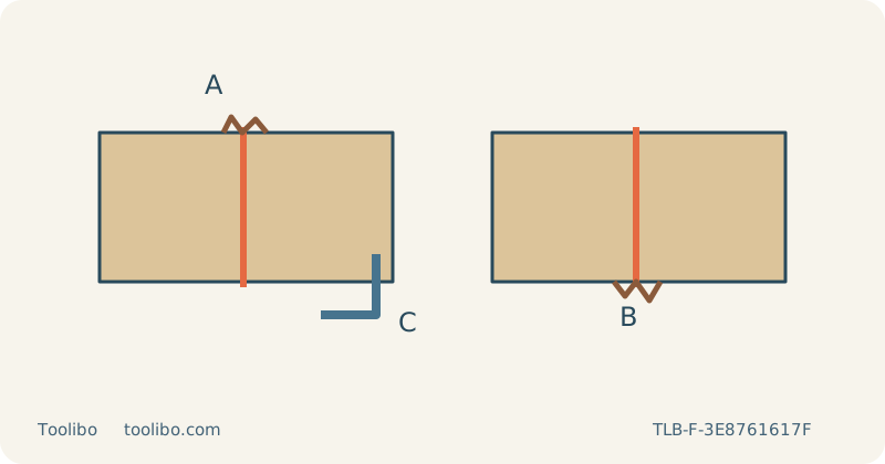
A
Mark the reference face
B
Inspect the opposite face too
C
Check edge fit separately
Separate base-cover protection, permitted splinter inserts and face orientation on matching scrap.
Decide which surface matters before cutting
A clean upper face does not guarantee a clean lower face, and a neat pencil line does not guarantee an undamaged edge. Before cutting a visible household panel, identify the face that will be seen and the edge that will be fitted. Mark them on a matching scrap sample as well as on the blank. This makes the comparison meaningful when the sample is turned over after cutting.
Use known, loose, uncoated wood or an identified panel suitable for the selected blade. Do not apply this procedure to unknown coatings or material installed over hidden services. The objective is a controlled comparison of face finish, not a universal rule that one orientation or one accessory prevents all splintering. Grain, panel construction and blade condition can change the result.
Separate the cover from the splinter-control insert
On the Makita XVJ03, the cover plate and anti-splintering device have different functions. The cover protects the surface from contact with the base; the insert supports material around the blade opening in its permitted arrangement. Treating the cover as a substitute for the insert can leave the edge unprotected, while treating the insert as a universal accessory can obstruct an incompatible setup.
Switch off and remove the battery before fitting either component or adjusting the base. Follow the XVJ03 instructions for the forward base position and insertion from the rear when fitting its anti-splintering device. That device is not used for bevel cuts. Use only a compatible component and never trim its opening or remove a guard to make a different blade fit through it.
Prepare two samples that differ in one way
Fit a sound blade specified for the panel and thickness, fully seated in the correct clamp with its back in the guide roller, and check retention. Secure the base at zero bevel. Mark the visible face and waste side. To compare face orientation, keep the blade, material thickness, support and cutting settings unchanged between samples. If several things change together, the cleaner edge cannot be confidently attributed to orientation alone.
Inspect the blade’s documented cutting direction and application rather than guessing from an unfamiliar tooth shape. This guide does not prescribe a reverse-tooth accessory for a particular saw. If considering a different tooth direction, verify that exact accessory’s requirements with its maker and the saw instructions first, then test its handling separately. Do not assume that a blade which changes the cleaner face also behaves identically under the base.
Protect the surface without hiding the route
Clamp the retained sample on a stable bench using suitable pads where needed to prevent clamp marks. Independently support the waste so it cannot tear away or close the kerf. Keep the full blade stroke clear below the board, and inspect both the underside and the complete base route before starting. Remove loose chips from the reference surface while power is isolated so the base does not ride over them.
Wear eye and hearing protection and suitable respiratory protection. Use compatible dust extraction and ventilation, with the hose or cord routed behind the tool. Start with low or zero orbital action as appropriate for the blade and intended finish. Support the base, keep the blade clear of the material, start and establish speed before feeding. Maintain flat contact without excessive downward force or sideways steering.
Inspect damage and fit independently
Switch off and wait for the blade to stop fully before withdrawing, setting down or turning over the sample. Remove the battery before any change. Examine fibre breakout on both faces, scratches in the surface and the squareness of the cut face. An accessory may improve one of these while leaving another unchanged. Do not call a sample successful merely because the visible face looks better if the mating edge is now outside its required size.
Choose the arrangement that meets the actual project need and record the reference face, blade and permitted insert configuration. Carry it to the finished blank only after rechecking thickness and workholding. Leave reasonable hand-finishing allowance where needed. If neither orientation gives an acceptable result with a suitable blade, choose another cutting method rather than progressively reducing the finished panel through repeated speculative cuts.
Models referenced