
Makita XVJ03: distinguish blade seating, cover and splinter insert · Diagram
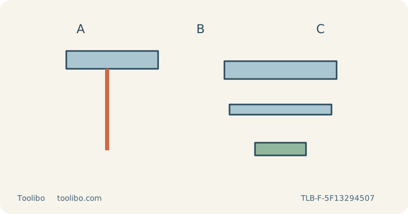
An inserted blade is separated from an exploded base, protective cover and smaller splinter insert.
A
Verify full insertion
B
Distinguish the cover
C
Check insert restrictions
An inserted blade is separated from an exploded base, protective cover and smaller splinter insert.
Separate the machine from its sales listing
Makita’s US XVJ03Z listing identifies the tool-only package, while the operating instructions name the XVJ03 machine. The checked product page marks XVJ03Z discontinued. That status does not establish that every accessory is unavailable or that an existing tool should be discarded; it does mean that a current shop listing is not a substitute for matching the machine and its manual before buying a replacement part.
This guide addresses a blade change and surface-protection setup for a straight sample in loose, known, uncoated wood. The base cover and anti-splintering device do different jobs. Treat them as separate decisions rather than fitting every piece found in a case. An accessory that appears to fit can still be inappropriate for a blade, base position or bevel angle.
Make the blade change a disconnected operation
Switch off, remove the battery and allow the blade to cool. Inspect the old blade for bends, damaged teeth or an unsuitable profile before deciding to reuse it. Follow the manual’s tool-opener movement to release it, keeping your fingers clear of the teeth and allowing for the blade to come free. Do not open the mechanism beyond its prescribed travel or use pliers to force a reluctant blade out.
For installation, open the tool opener as shown in the instructions and insert the correct blade with its teeth facing the cutting direction. The blade goes fully into the clamp until its two protrusions can no longer be seen. Keep its back in the roller and return the opener to its original position. With power still removed, check secure retention as directed. If proper seating or return movement is uncertain, stop and obtain service advice.
Choose protection for the actual surface
The cover plate protects a sensitive face from contact with the base. Check that it is clean and is the compatible part before fitting it to the base as instructed. A trapped chip between the cover and the work can still mark a panel, so surface protection does not eliminate the need to inspect and clean the contact area. Do not improvise thick padding that changes how securely the base rests.
The anti-splintering device supports material near the blade opening. For the documented XVJ03 arrangement, move the base fully forward and fit the device from the rear. When the cover plate is used, the device fits onto that cover. The anti-splintering device cannot be used for bevel cuts. Do not enlarge its opening, remove a guard or force it around an incompatible blade to obtain a combination that the manual does not permit.
Test the complete arrangement on scrap
With the battery still removed, secure the base at zero bevel and check that the blade remains suitable for the full material thickness throughout its stroke. Clamp a representative offcut to a stable bench and support the waste independently. Leave the entire moving blade clear underneath, and inspect the base route above for clamp collisions. Keep the hose behind the saw so it cannot pull the cover across the surface sideways.
Wear eye and hearing protection and suitable respiratory protection. Use the compatible dust arrangement and ventilation. Choose speed and orbital action appropriate to the blade and wood; begin with low or no orbital action when assessing an exposed edge. Support the front of the base, start with the blade clear of the material and establish speed before feeding. Keep the base flat without forcing the teeth through a difficult patch.
Assess scratches and splintering separately
Switch off and wait for the blade to stop fully before withdrawing it, setting the tool down or turning over the sample. Remove the battery before changing the setup. Examine both faces for breakout, the surface for base marks and the cut face for squareness. A clean upper face alone does not prove that the chosen blade and support will produce the required mating edge.
If the result is poor, change one relevant factor at a time. Remove trapped debris, replace a worn blade or revise support before concluding that another accessory is needed. Preserve a successful sample with its reference face marked, and recheck the configuration whenever the base angle changes. If the clamp will not hold, the opener will not return normally or the base will not stay secure, take the saw out of use rather than relying on a protective cover to hide the underlying fault.
Models referenced