
Leave room to hold and withdraw
Cabinet cross-section shows axial withdrawal, hand envelope and a disconnected battery footprint.
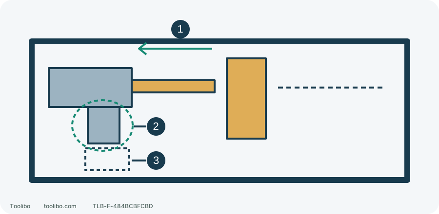
1. Axial exit
The bit must be able to leave the completed hole without sideways levering.
2. Grip clearance
Keep a secure grip with fingers clear of the rotating chuck.
3. Battery envelope
Measure its real space while the battery stays removed.
Not to scale. Check the real bit, workpiece, hand and battery without connecting power; the drawing does not clear hidden services.
Check safe access, not just whether it squeezes in
This concerns the North American PSBDD02 and controls/tool lights in 999000220 REV02. It is a drill/driver, not a hammer drill. A smoking, leaking or rapidly and abnormally heating battery means move clear, not ordinary disassembly.
With stable equipment safe to handle, release the trigger, wait for standstill, centre-lock the direction selector and remove the battery. Fit the intended accessory normally, then rehearse entry, axial alignment and withdrawal with the isolated tool. Do not reinstall a powered battery merely to measure clearance.
Check three real locations: can the tip reach along the working axis, can you grip securely with fingers clear of the chuck, and can tool and accessory withdraw afterward? Include the actual battery envelope by measurement even while it is removed. If you must push sideways, trap a hand between tool and cabinet or cannot withdraw the bit afterward, reposition the work or change the method before starting.
Raise the nose and seat the accessory by hand
- Keep the battery removed and trigger locked. Check that the shank is sound and compatible.
- Follow the chuck arrows to open the jaws slightly wider than the shank by hand; do not use a wrench.
- Raise the tool’s nose slightly and insert the accessory straight so it does not fall out. Grip the suitable shank, not a crooked insertion pulled straight by tightening.
- Turn the sleeve by hand in its marked tightening direction and secure it. Never hold the sleeve and run the motor to tighten it.
- Still isolated, check for obvious crooked seating, looseness or pull-out. Unreliable seating after refitting, damaged jaws or abnormal sleeve movement means stop using and arrange inspection, not shims.
A shorter accessory may improve access, but must still suit the job, chuck and screw recess. Fitting the shank does not authorise a particular hole diameter, material or extension assembly.
Trial low gear; “24 positions” are not all clutch numbers
The top selector’s 1 is the low-speed/high-torque range, listed for screws and metal drilling; 2 is the higher-speed range for suitable faster drilling tasks. Shift only after complete standstill, never under load. Remove the battery for accessory preparation and inspection.
The torque table groups 1–4 for small screws, 5–8 for soft material, 9–12 for soft/hard material, 13–16 for hardwood and 17–23 for large screws, with a separate drilling position. These are model-specific selection cues, not strength guarantees or 24 calibrated torque readings. Do not jump to drilling simply because a screw will not advance.
Different product-page fields give 1700 versus 1750 rpm at high speed. That discrepancy should not dictate work in a corner. Select the range from the correct tool markings and control the trigger within material/accessory limits; no performance or version inference is drawn here.
Establish depth on scrap
Clamp matching nonstructural scrap and prepare the screw’s required pilot. With the battery removed, fit the driver and choose gear 1 with a low numbered clutch setting. Check access and workholding. Keep your finger off the trigger, insert a compatible battery and confirm both side latches. Select correct driving direction from the markings; centre lock is not the running position.
Seat the driver fully in the recess and along the screw axis, then pull gently for slow driving. Release near target depth rather than letting the tool keep sinking the head.
- Clutch releases before seating: stop, remove the battery and check pilot, fit and alignment before increasing the clutch one small step.
- Correct depth with sound screw and material: retain the setting for identical conditions; repeat the trial if material, screw or joint thickness changes.
- Cam-out, splitting, excessive depth or stalling: release immediately, stop and isolate safely to investigate, rather than increasing settings and force.
After each adjustment, recheck, reinstall and secure the battery with your finger off the trigger, then select correct direction before another trial. The final location still needs full grip and exit clearance; success on scrap does not establish that an unknown cabinet wall is free of wiring.
What the tool light says after an existing stop
Do not recreate stops to count flashes. This table concerns an already-observed PSBDD02 base LED, not a charger and not all RYOBI tools.
Swipe or scroll horizontally to see all columns.
| Observed display | Manual meaning | Response |
|---|---|---|
| Steady, no flashes | Normal lighting | Still assess operation; illumination does not prove correct bit fitting |
| 3 flashes | Low battery | Stop and remove safely; use a compatible, sound charged battery |
| 6 flashes | Excessive force | Release the trigger; the manual says wait 5 seconds, but correct the overload cause before resuming |
| 9 flashes | Over-temperature | Stop and cool naturally; cooling does not clear damage or abnormal heating |
For more than 9 flashes, the manual separately specifies battery removal and reinsertion a few minutes later. That assumes stable equipment safe to handle and does not replace investigation. Unknown codes or causes, damage, or the same fault recurring after recovery mean stop using and arrange inspection.
Models referenced